Issue:
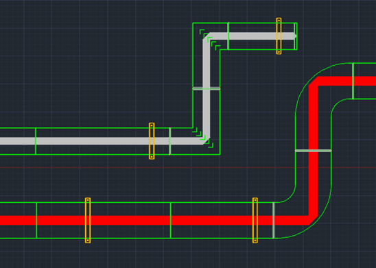
When routing a duct with Design Line, the bends automatically default to a square bend for all duct sizes. You may want to have the square bend from a certain duct size to a certain duct size and a radius bend for times when a duct is greater than a specified size. For example, you may want a square bend for all runs, unless the duct size exceeds a specific size (i.e., 12" ducts), then have it put in radius bends in place of square bends when the duct size is equal or greater than 12”.
Solution:
These settings can be changed under Edit Service Template.
1. Open the Setup Service dialog by selecting on Edit Service Database.
![]()
We will be making these changes for Supply Air service.

2. Select Edit Service template icon
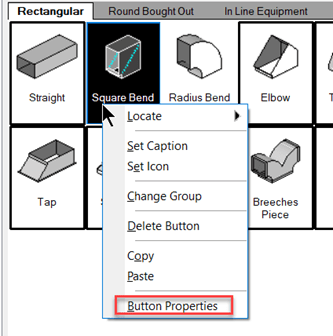
3. Right click over the Square Bend and select Button Properties

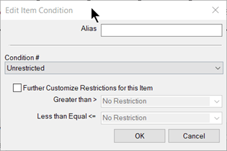
4. In the Button Properties dialog box double click on Square Bend.ITM. The Edit Item Condition dialog box opens.

5. Under Condition #, under the list and select on the conditional option that best works for your design. We will select up to 12”. There are farther restriction options to do greater than to less than or equal to values. For example, greater than (>) 1” but less than or equal to (<=) 12”

6. Right click on the radius bend and select Button Properties.
7. One key option to change is the Button Code to Bend. If the Button Code is not change then when running a duct run usings Design Line the elbow will always default to the square bend.
8. In the Button Properties dialog box double click on Square Bend.ITM and in the Edit Item Condition dialog box select the list under Condition # and select greater than 12”.
9. Select OK to all dialog boxes.

Note: These changes will affect all sessions of Fabrication Design Line layouts. To set this option as a new Service see blogs.
Duplicate the folder for the items (in this case rectangular duct.). You can also manually copy the folder using File Explorer by navigating to C:\Users\Public\Documents\Autodesk\Fabrication 2024\Fabrication Imperial 4.02 Demo\Items\Imperial Content\HVAC\Generic\Systems
Fabrication CADmep 2024 used for this example
https://resources.imaginit.com/support-blog/pathing-folders-in-the-fabrication-database
and then use this link to create a new service and associate the new Item folder for the fittings.
https://resources.imaginit.com/support-blog/creating-a-fabrication-cadmep-service
About the Author
Follow on Linkedin More Content by Paul Sills


