

Issue: iPart Replacement Can Break Assembly Constraints
When an existing iPart occurrence in an assembly is replaced with another member from the same iPart factory, existing assembly constraints can become unresolved.
This can occur even when the replacement member has the same geometry and only differs in something such as material.
Causes: Constraints Reference Specific Geometry
Inventor assembly constraints reference specific geometry, such as faces, edges, and work planes.
When an iPart member is replaced, the corresponding geometry in the new member can have different internal references. Inventor may therefore no longer recognize the geometry as the same reference used by the original constraint.
This can result in unresolved constraints that must be repaired manually.
Solution: Convert iParts to Model States
Model States provide an alternative way to manage multiple configurations within a single Inventor part file. Instead of replacing an assembly occurrence with a different iPart member, the same part occurrence can be configured using different Model States.
This can help avoid constraint-reference issues associated with replacing iPart members.
Converting an iPart to Model States
1. Back Up the Existing iPart
Create a backup of the iPart factory and its associated files before making changes.
2. Export the Existing iPart Data
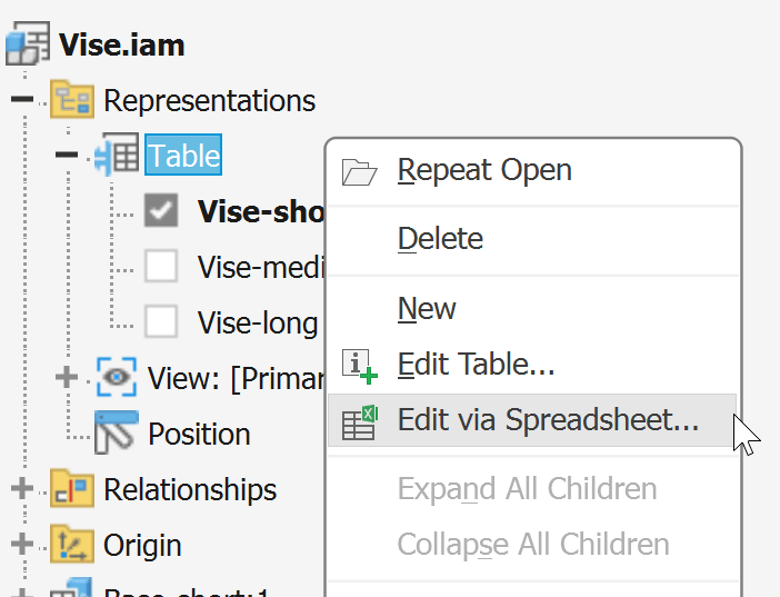
Open the iPart Factory, expand Table in the Model Browser, right-click the table, and select Edit via Spreadsheet. Save a copy of the spreadsheet and close Excel.
3. Delete the iPart Table
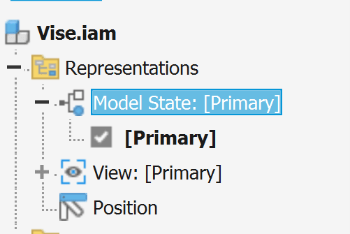
Return to Inventor, right-click Table, select Delete, and save the part. The Model States folder should then become available.
4. Create the Model State Table
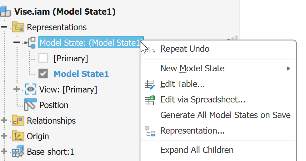
Expand Model State and create a New Model State. Then right-click the Model State folder and select Edit via Spreadsheet.... The Model State spreadsheet will open with the existing Model State information. Add the remaining configurations from the original iPart spreadsheet and enter the original iPart member names in the Member column.
5. Transfer the Configuration Data
Copy the applicable configuration information from the original iPart spreadsheet into the Model State spreadsheet, including dimensions, materials, feature suppression, part numbers, descriptions, and applicable iProperties.
6. Exclude iPart-Specific Tags
Review the spreadsheet and exclude iPart-specific tags such as <key>, <filename>, <material>, and <defaultRow>.
7. Verify the Model States
Check geometry, dimensions, materials, feature suppression, part numbers, descriptions, and iProperties against the original iPart.
8. Test in an Assembly
Replace the existing iPart occurrence with the converted part and select the appropriate Model State. Switch between several Model States and verify that the existing assembly constraints remain functional.
Important: Test representative parts and assemblies before converting an entire iPart library. Model States can still affect constraints if the selected state suppresses or changes geometry referenced by an assembly constraint.
About the Author
More Content by Harpreet Waraich


