
Issue:
In Revit, you may find that you need a custom fabrication part to accurately model a specific component in your project. However, Revit does not include a built in feature that allows users to create new fabrication parts from scratch. The fabrication parts available in Revit come directly from the Fabrication CADmep/ESTmep/MEPcontent databases, and Revit can only use the parts that already exist in those databases.
Because of this limitation, any custom fabrication part must be created or modified within the Fabrication software environment (such as Fabrication CADmep) before it can be used in Revit. Once the part is created in the fabrication database, it can be loaded into Revit and used like any other fabrication component.
This workflow ensures consistency between fabrication modeling and shop ready content, but it also means Revit alone cannot generate new fabrication part geometry or behavior. Users who need highly specialized or non standard parts must rely on the fabrication database tools rather than Revit’s native modeling tools.
Solution:
First, we need to identify the correct CID number to use when creating a custom part. By going to Help | Common Pattern Numbers (CIDs) | Autodesk, you can review the list of CIDs used for creating pipe, HVAC duct, and electrical parts. However, the list on the site is not complete. A more reliable method is to use the Folders command to navigate directly to the templates and view all available CIDs.
1. Open the Item Selector
Type folders to open the Item Selector.
Navigate to the Template CIDs
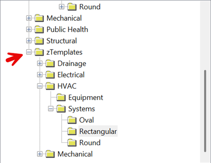
In the tree view, navigate to:
2. zTemplates → HVAC → Systems → Rectangle
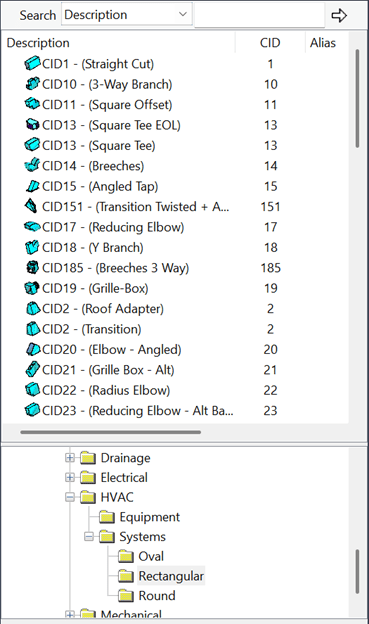
This will display the CID list for rectangular ductwork, including the CID numbers and preview images of the associated fittings. If the view appears cluttered, right click and select Views → Auto Arrange to organize the items clearly.
3. Create the Part Using the CID
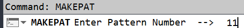
Once you identify the CID number for the part you want to create, type makepat, press Enter, and then enter the CID number. For this example, we will use CID 11.
4. Configure the Part in the Makepat Dialog
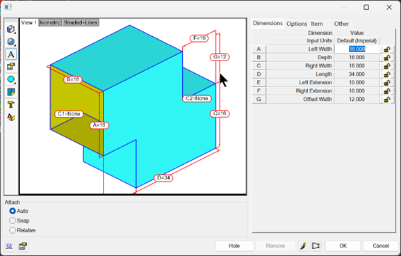
In the Makepat dialog box, adjust the sizes as needed on the Dimensions tab. To better orient the model view, hold the left mouse button in the preview window and move the mouse to orbit the fitting. The dialog contains several tabs:
• Dimensions – Define the dimensions based on the labeled letters and values shown in the preview image.
• Options – Displays additional settings depending on the CID. For example, you can turn off the main duct when using a tee CID to create a tap.
• Item – Set specifications such as insulation spec, materials, and other item properties.
• Other – Define the connection type for each end of the fitting.
5. Save the Part to the Fabrication Database
Select OK to save the part into the fabrication database/catalog.
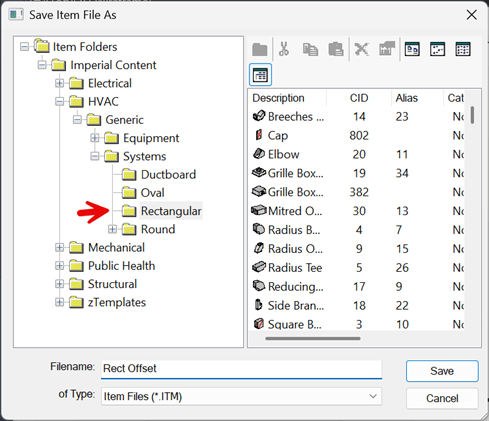
Navigate to:
Imperial Content → HVAC → Generic → Systems → Rectangular
Enter the item name (e.g., Rect Offset) and select Save.
Adding the Part to a Service
To make the new part available in Revit, it must be added to a service.
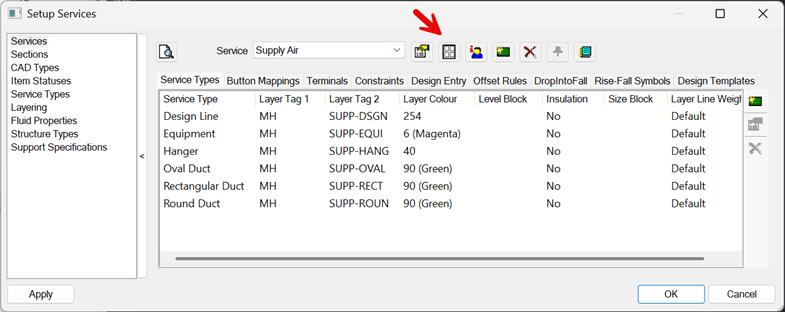
1. Open the Service Database
Select the Edit Service Database icon, typically located at the top center of the screen.

2. Edit the Service Template
In the Setup Service dialog box, select Edit Service Template.
3. Add the Part to the Service
In the Edit Service Template window, navigate to Rectangular on the left side. Drag and drop the newly created part (Rect Offset) into the service on the right side.
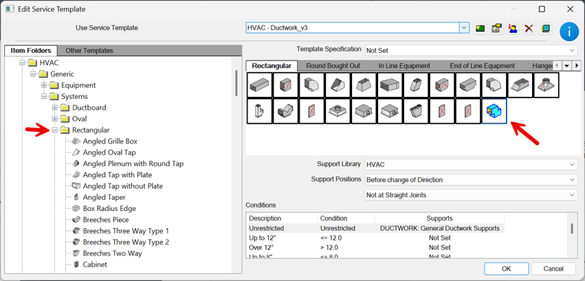
4. Save Changes
Select OK to close both dialog boxes.
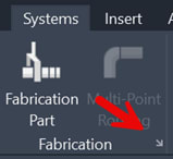
In Revit
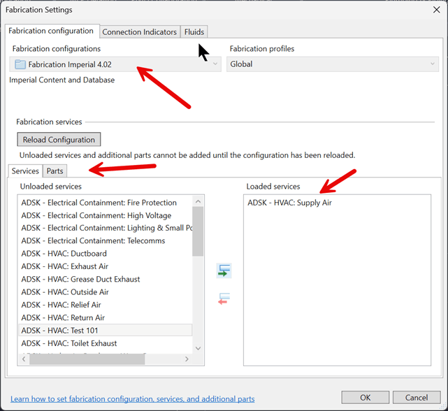
1. In Revit, click the Systems tab. In the Fabrication panel, select the Fabrication Settings arrow in the lower right corner of the panel.
2. In Fabrication Configurations, select the database you want Revit to use.
3. Under Services load ADSK-HVAC Supply Air to add to Loaded Services and then select Ok
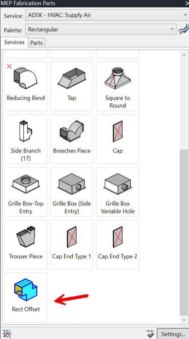
4. Select Fabrication Part.
5. Under Fabrication Part, the newly created Rect Offset is now available for use in Revit.
About the Author
Follow on Linkedin More Content by Paul Sills


