
This post will offer solution to display linear data on Section Views. One of our previous post demonstrates how to use Corridors to highlight Right-of-way locations:
The goal here is to explore simple ways of displaying existing or proposed geometry in section views:
• Buried Utilities (Gas, Water, Communication, Etc..)
• Surface Feature Location (EOP, BOC, TOP, TOE, Etc..)
• Site Features (Fence, Building, Guardrail, Etc..)
The answer is to project Feature Lines to Section Views, without having to build complex Civil 3D elements such as Corridors or Pipe Networks.
The power leveraged here is in the style configuration behind the scenes, below are 2 options.
Scenario 1: Multiple Feature Lines with assigned Marker styles
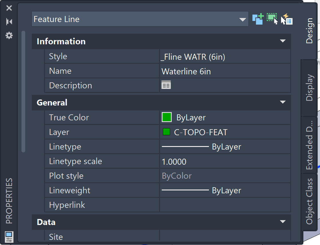
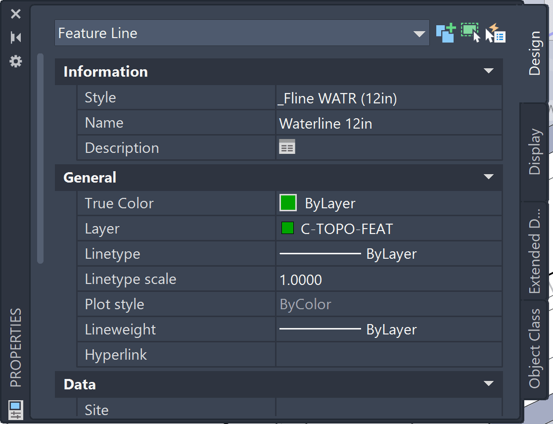
One option is to create multiple Feature Lines individually configured layers for color & linetype (plan view). Along with matching Marker styles with blocks (section views). The table below shows the configuration for a 6” and 12” waterline.
| 6” Waterline Feature (unique) | 12” Waterline Feature (unique) |
|
AutoCAD Object Property: the feature resides on a green C-TOPO-FEAT layer - that Civil 3D ignores for display
Civil 3D Style: Sets blue layer & linetype, along with matching Marker with 6” block.
|
AutoCAD Object Property: the feature resides on a green C-TOPO-FEAT layer - that Civil 3D ignores for display
Civil 3D Style: Sets blue layer & linetype, along with matching Marker with 12” block.
|


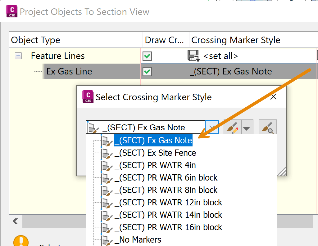
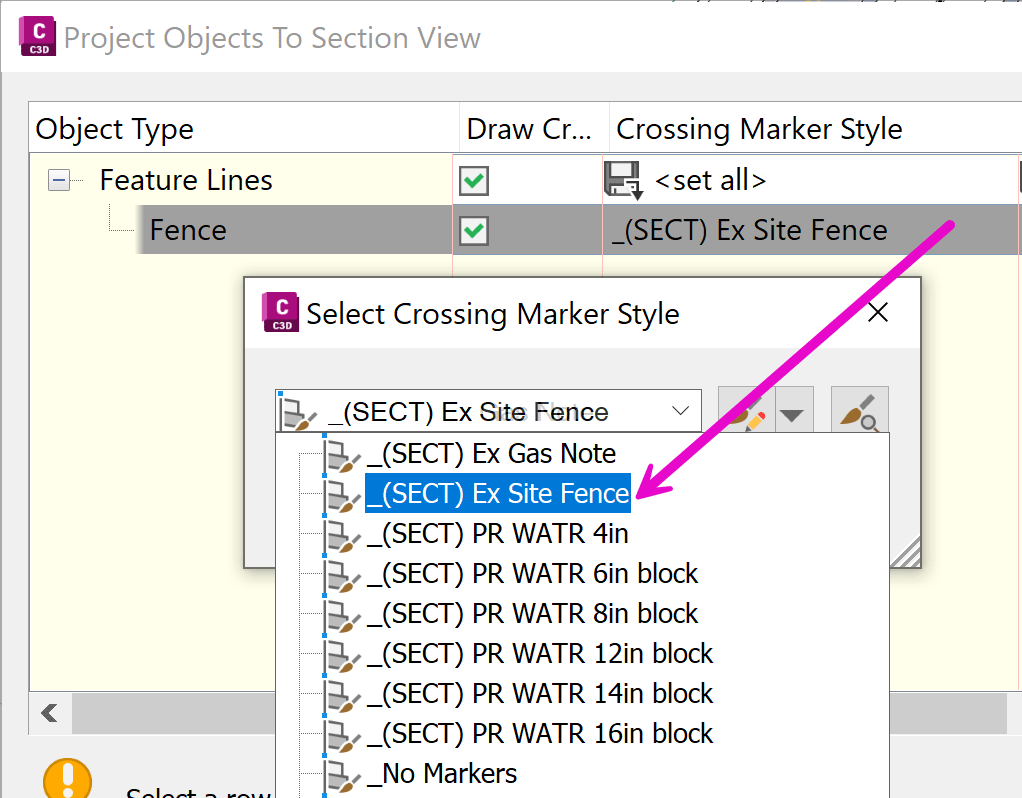
The method of display in Section Views is done by > Projecting Objects To Section View > from dialog box > Crossing Markers Styles > from drop down > scroll to bottom of list and select: <Use Object> 
Feature Lines here have been set are set to specified surface depth, and the applied configurations displays the needed Plan and Section View looks: 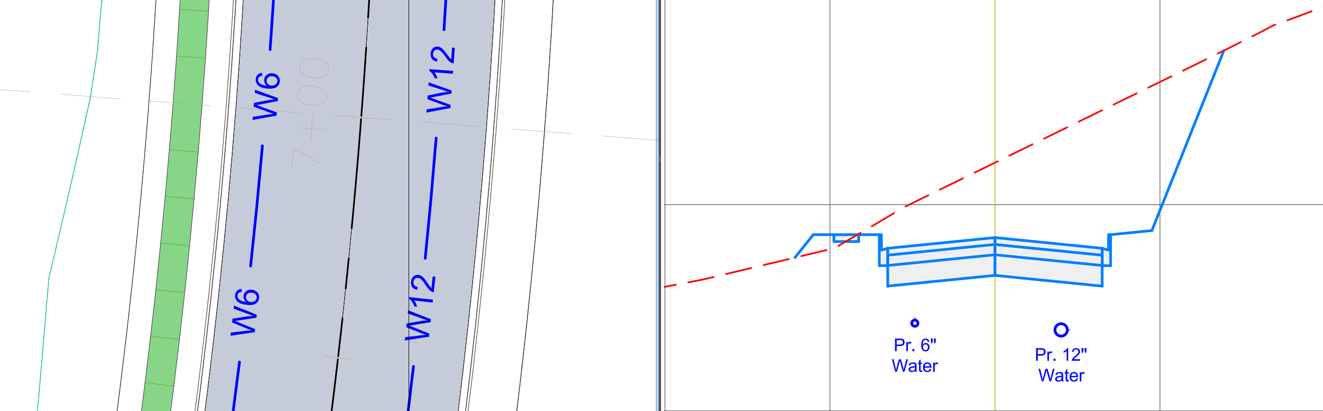
This method requires a unique Feature Line and Marker Style for each. As shown a 4”, 6”, 8”, 12”, 14” and 16” Waterline types were created. This method could yield a robust list of Feature Line and Marks styles to for each type, size and orientation (gas, storm, sewer, water, etc…).
Scenario 2: Single Generic Feature Line, with matching Marker Styles
Another option is to set up a single Feature Line style, configured to layer 0. This would rely on the AutoCAD “By Layer” behavior, where linework would need to be placed on the correct layer manually by users (plan view). Along with complementing block set up needed for Marker style display (section views).
The example below shows configuration for a Gas and Fence features:
| Gas Line – Feature Line (same) | Fence Line – Feature Line (same) |
|
AutoCAD Object Property: the feature resides on a orange C-UTIL-NGAS layer - that Civil 3D follows.
Civil 3D Style: Set to layer 0 and Marker to
|
AutoCAD Object Property: the feature resides on a purple V-SITE-FNCE that – that Civil 3D follows.
Civil 3D Style: Set to layer 0 and Marker to
|


The selected AutoCAD layers will control the look (color & linetype) of Feature Line. The display in Section Views is from Feature Lines set to the necessary surface elevation and the selection of the corresponding Crossing Marker Style during the projection command:
| Gas Line – Marker (unique) | Fence Line – Marker (unique) |
|
The display for GAS Markes will be assigned when adding to Section views
|
The display for FENCE Markes will be assigned when adding to Section views
|
As shown, things come together from Plan to Section views with use of a Single Feature Line style. 
However, this method still requires unique Marker styles to be set up for each projected object type, size and orientation.
I hope you can apply one of these 2 configuration and projection methods to display linear data on Section Views.
About the Author
More Content by Leo Lavayen


