
This post will review overlapping Alignment and Profile label styles and options designers have.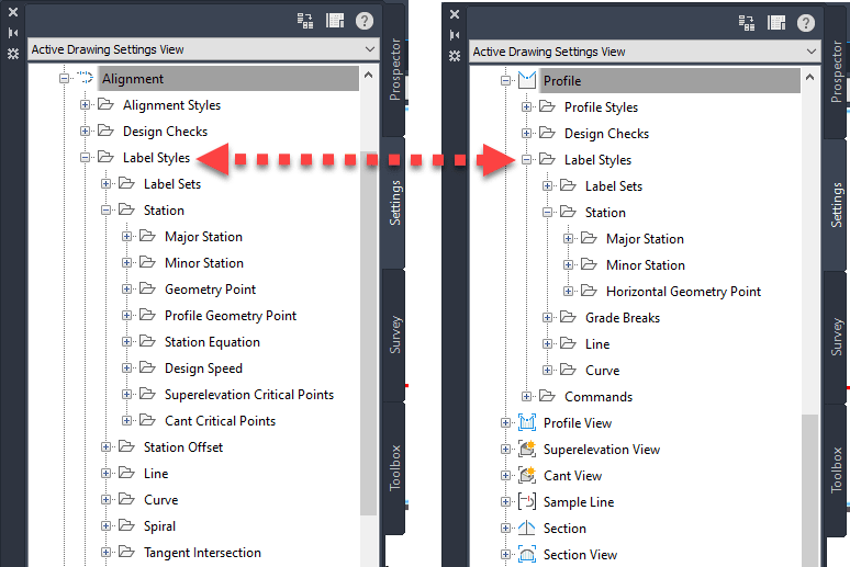
Density in design or selected drawing scale, or zoom level can all influence how annotations look like. Let tak a lok at these 3 catagories:
• Alignment: labels are overlapping Station and Geometry
• Profile: grade break labels
• Profile Band: major elevations 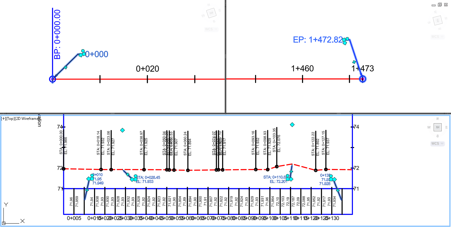
Relocating Alignment Labels:
For the Alignment, the Station (pink) and Geometry (blue) labels are repositioned. It is a simple AutoCAD grip edit > select square grip label > move out of the way:
With appropriate configuration, the look and behavior of the resulting label is controlled by the Dragged State Component selection for Display:
• As Composed: will keep any line or block components, keeping its default look.
• Stacked Text: will drop any line or block component, and even its readability. 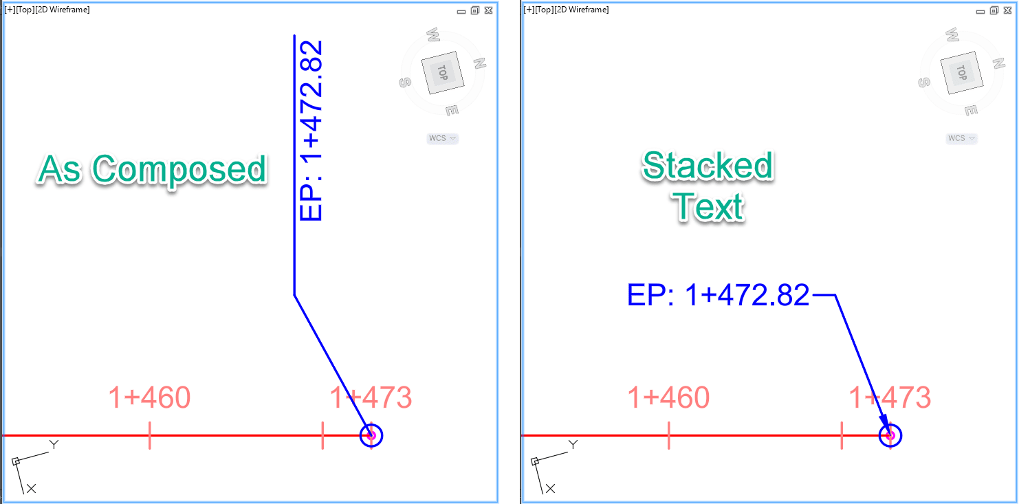
To set any annotations back to their default location, use the “Reset” option from the right click menu or contextual ribbon: 
Relocating Profile & Band Labels:
Profile Line labels PVI's (black) and Band annotation (green) can also be grip edited and out the way and reset as was done with alignment.
Other than grip editing, the software does provide some options to automatically “Stagger” labels out of the way. If we focus on the Profile Grade Break labels, set below to: No Staggering 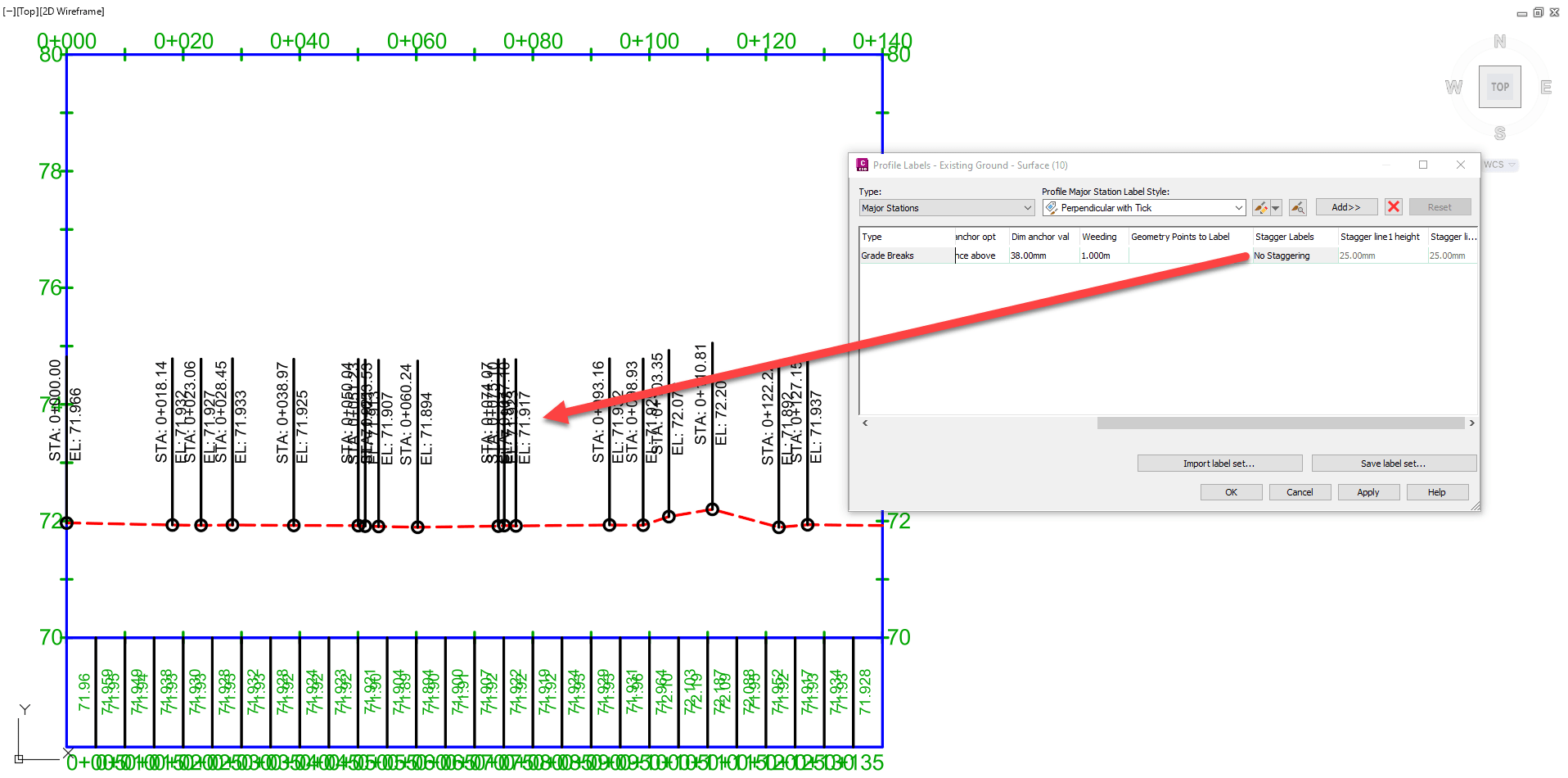
There are options to Stagger to Left, Stagger to Righ, Stagger Both Sides
Profile Bands offer a similar option to “Stagger” function. Again, here there are staggering options for: Left, Right and Both Sides
We hope you found thies reminders helpfull. IMAGINiT can help If you need help with setting up or understanding how software configuration works.
About the Author
More Content by Leo Lavayen


