
While creating Assemblies in Civil 3D, it is possible to call out individual lane values using the same subassembly. This post explores 2 options in assembly design.
OPTION 1: LANE SUPERELEVATION AOR SUBASSEMBLY
This is a very simple design example, here only 2 pavement depths are need for each side. Let's see how to leverage the default pre-defined LaneSuperElevationAOR subassembly to calculate individual values. As shown in the Civil 3D Help file, the subassembly has 4 pavement depth sections:
• Pave1
• Pave2
• Base
• SubBase
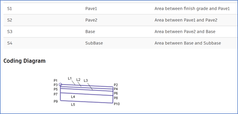
In this design example only use 2 depths (shapes) are used for each side. To keep values separate different values will be used:
• Left Side: Pave1 & SubBase
• Right Side: Pave2 & Base
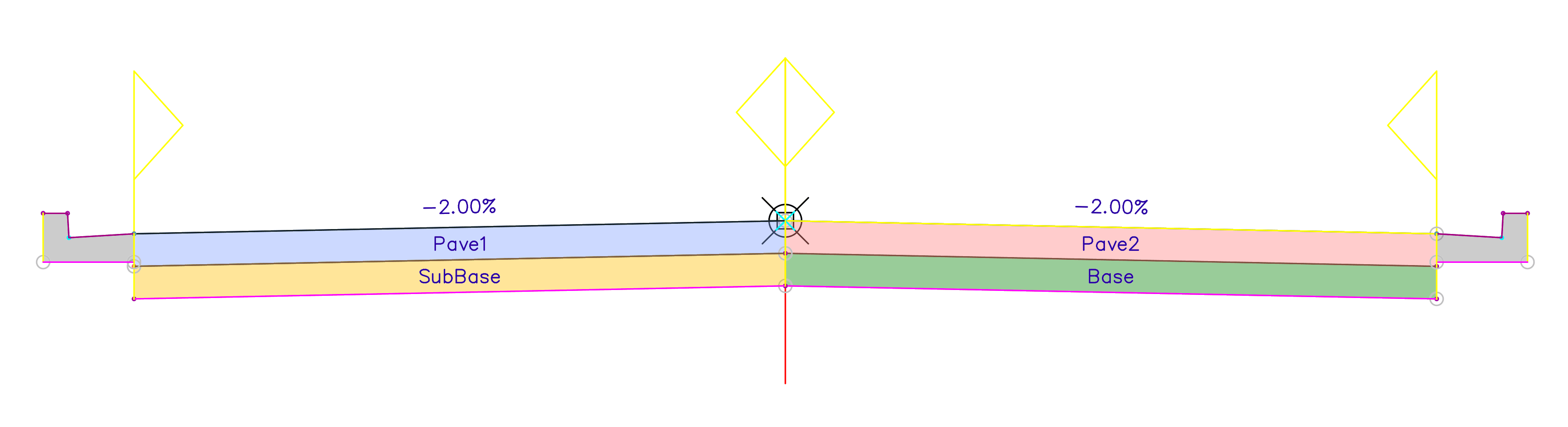
This allows for Computing of Materials calculations of all 4 sections of pavement: 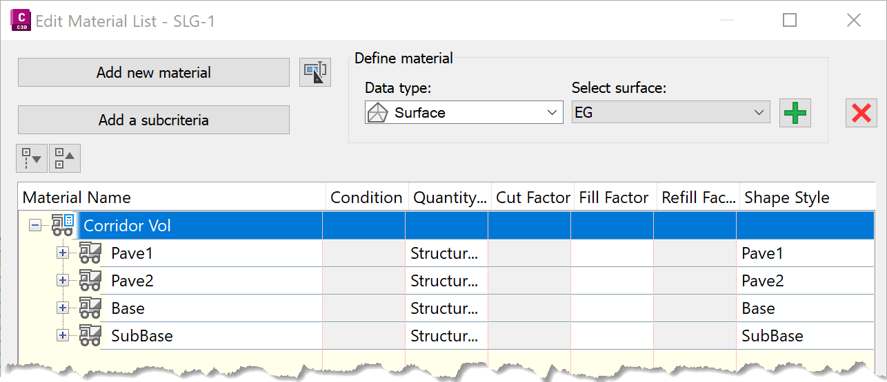
OPTION 2: GENERIC PAVEMENT STRUCTURE SUBASSEBLY
If more pavement elements are needed, different depths can be called out by using an editable subassembly: GenericPavementStructure. From the Civil 3D Help file and by looking at it Properties (image belwo), users can assign Point, Link and Shape codes. As shown below, the default appears as “None” for all fields. 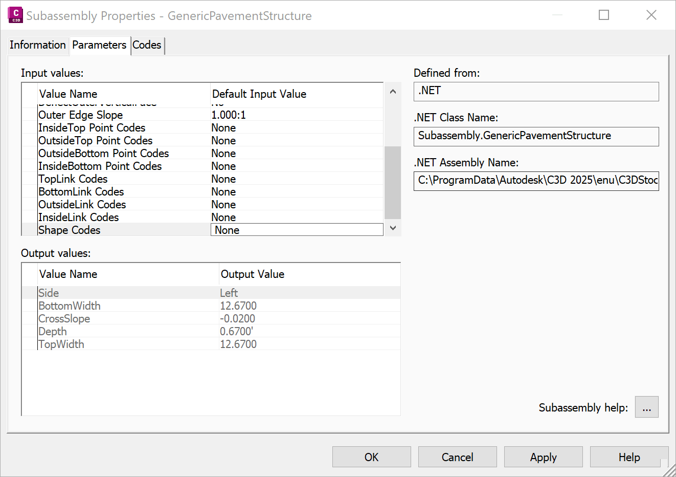
As it is a singular level depth structure, multiple will have to be added staked onto one another. As a reference there is a post that shows how-to reference values form one subassembly to another:
https://resources.imaginit.com/videos-webcasts/c3d-subassembly-reference-values 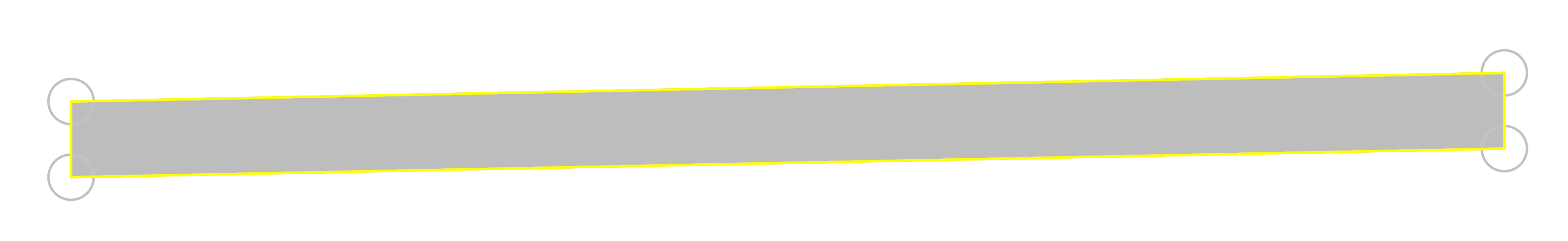
With no coding assigned to the subassemblies, the built assembly might look too simple to start with: 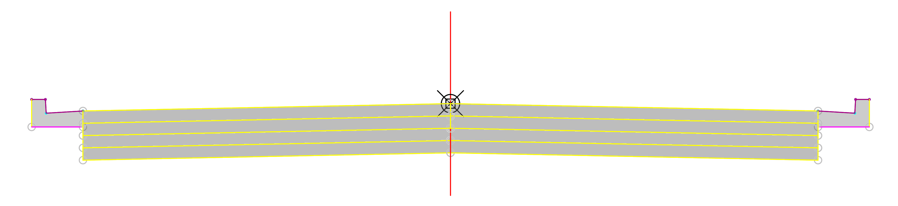
With a bit of effort and working with the configuration the assembly can come to life. Calling out needed Links, Points and Depths with colors and labels: 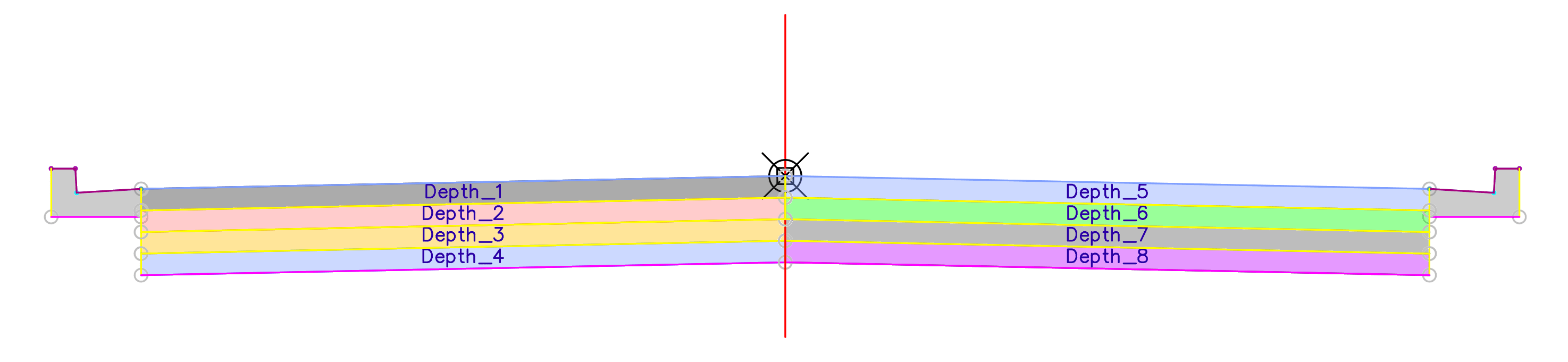
Again, because of the individual corridor elements, volumes can be computed for each material: 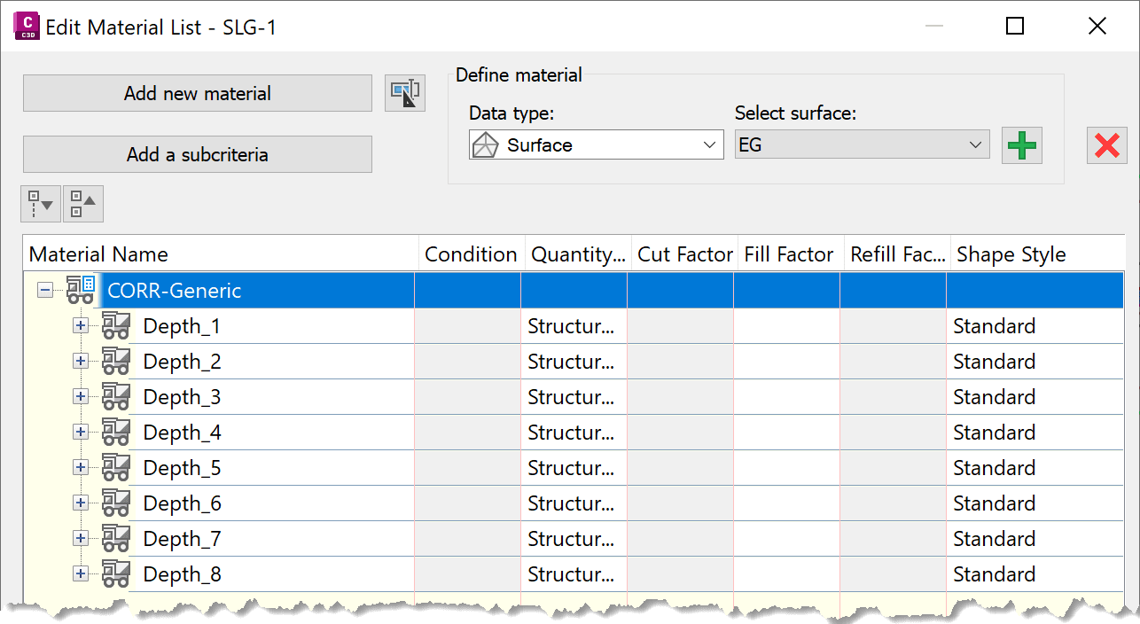
I hope you enjoyed this write up. If complex design and configuration is something you are struggling with IMAGINiT can help you.
About the Author
More Content by Leo Lavayen


