
In the first post, the option to apply varying grade values was explored using the NEW corridor transition functionality. This post will address how to apply the same station and grade values to the opposite right lane
As it stands, transitions have already been applied to the Left Lane (north side): 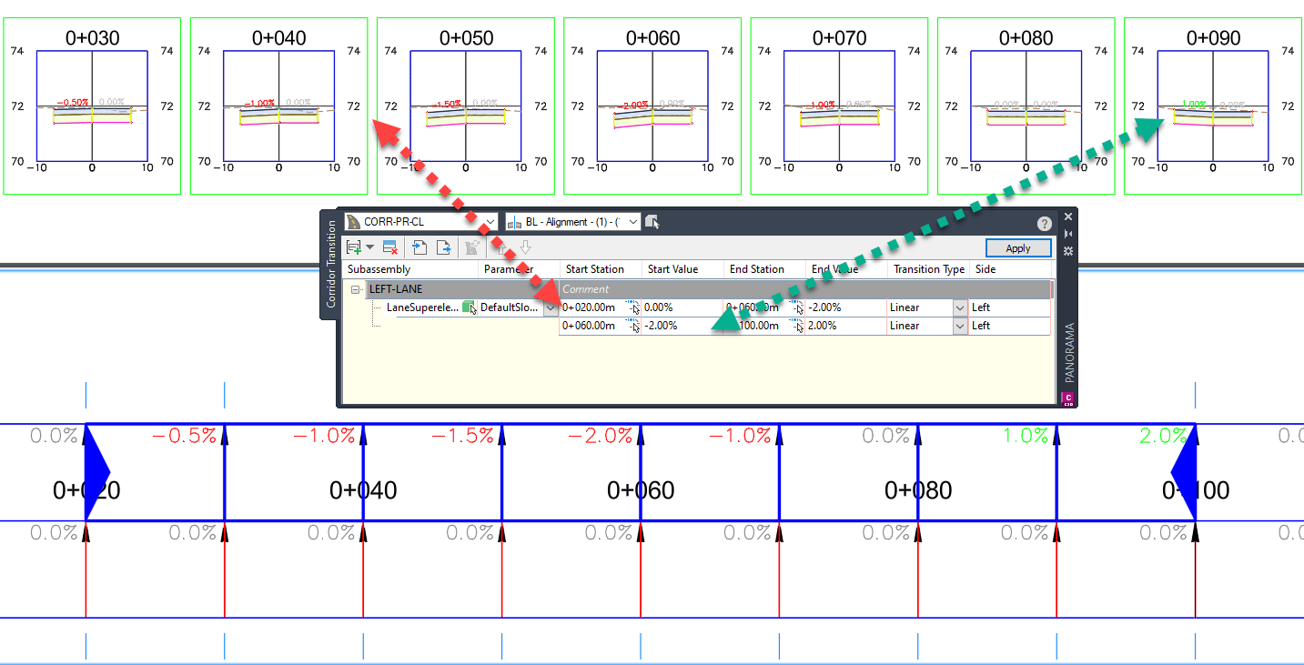
Note: configuration in this drawing has been made to automatically change label COLORS for slope values.
OPTION 1: Copy and Paste Transition Set:
For the purpose of clarity, the northern lane transition was rename to “LEFT-LANE”. Select the row, copy then paste the transition set. 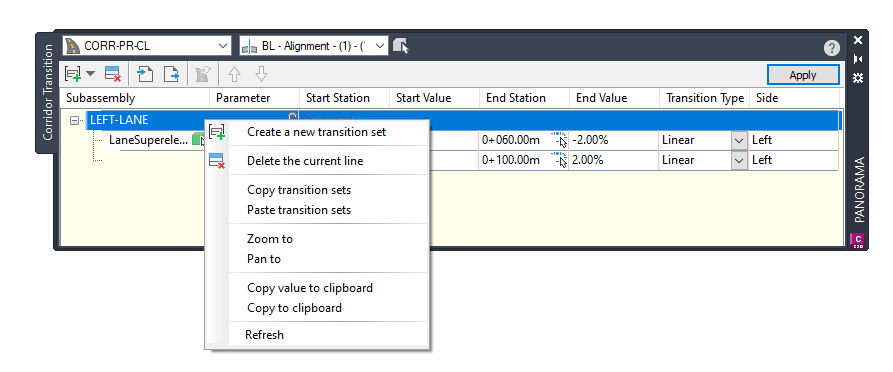
After pasting, a new row is added:
• For clarity, the row is renamed “RIGHT-LANE”.
• Click on the green box to select on screen the right lane in corridor (south pavement).
• Don’t forget to click on the Apply button. 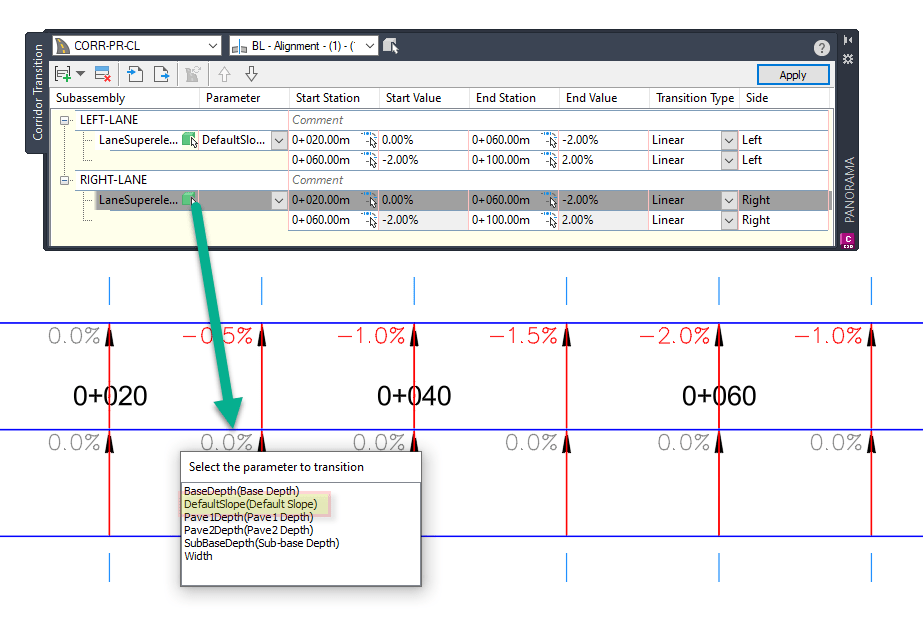
With the new values added and applied , the Panorama > Corridor Transition tab shows that values are mirrored on the LEFT and RIGHT sides: 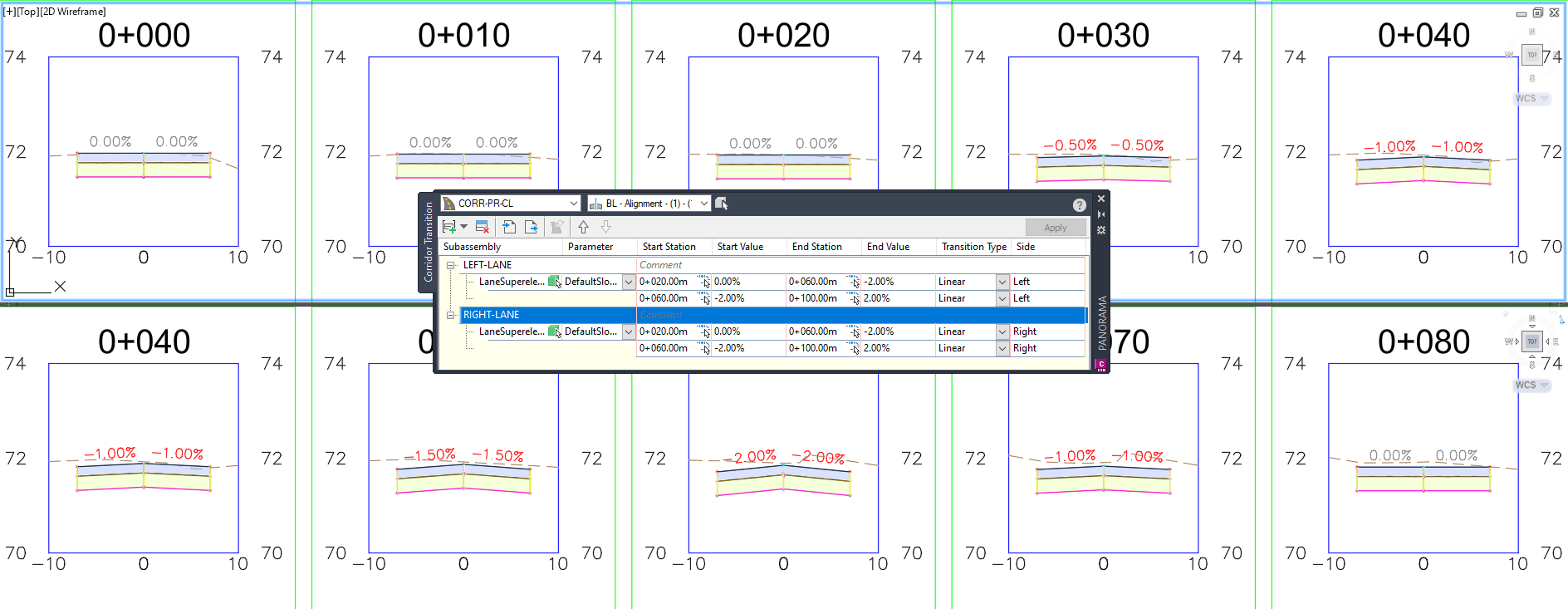
Note: configuration in this drawing has been made to automatically change label COLORS for slope values.
OPTION 2: Export, Edit and Import Values:
From the Panorama > Corridor Transition > the existing LEFT-LANE is shown. From the top row > select the Export transition button. Here the files is named: LEFT-LANE.csv 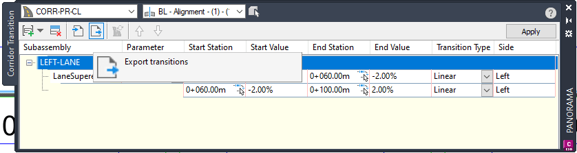
The created .csv file can be opened and edited. More rows can be added to the exiting design or new transition subsets: 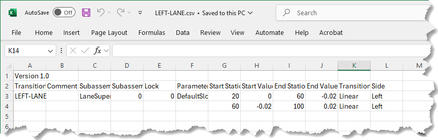
To preserve the original a copy of the file is made (BOTH-LANES.csv). While performing edits to the .csv, the existing format MUST be followed. See how a NEW lane is added: 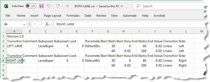
Now from Civil 3D, the edited (BOTH-LANE.csv) file can be imported. Note that the if transition are already in place a message about overwriteing them will pop up. This is why the original data rows must be kept. 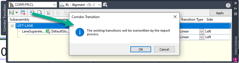
Once the file is read > click on the Apply button. As shown values are now mirrored on the LEFT and RIGHT sides:
Note: configuration in this drawing has been made to automatically change label COLORS for slope values.
In both cases shown above, if the negative and positive values are flipped for the RIGHT-LANE, a superelevation can be created:
Note: configuration in this drawing has been made to automatically change label COLORS for slope values.
Hope you found this part 2 write up help full! If you would like to work with the drawing, download the source file.
If you enjoyed this post, visit our IMAGINiT support page for similar content.
About the Author
More Content by Leo Lavayen


