
This post will review the Daylight subassembly called Stripping Top Soil. The subassembly is used to specify stripping of top soil to a specified depth. Details directly from the Autodesk HELP file.
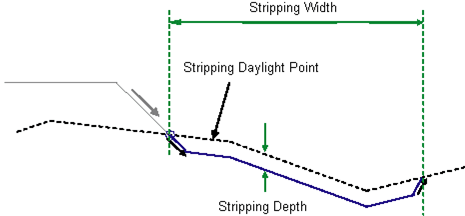
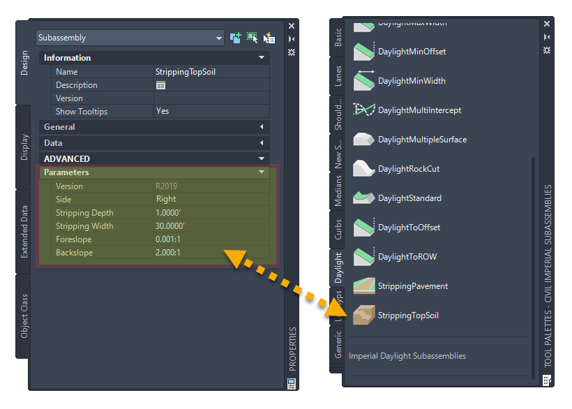
From the help file we learn that “This subassembly is used to specify stripping of top soil to a specified depth”. The Subassembly has been configured the follow way for this example:
We will be exploring two design scenarios and results:
• Simple Design Width
• Roadway Section with Daylight 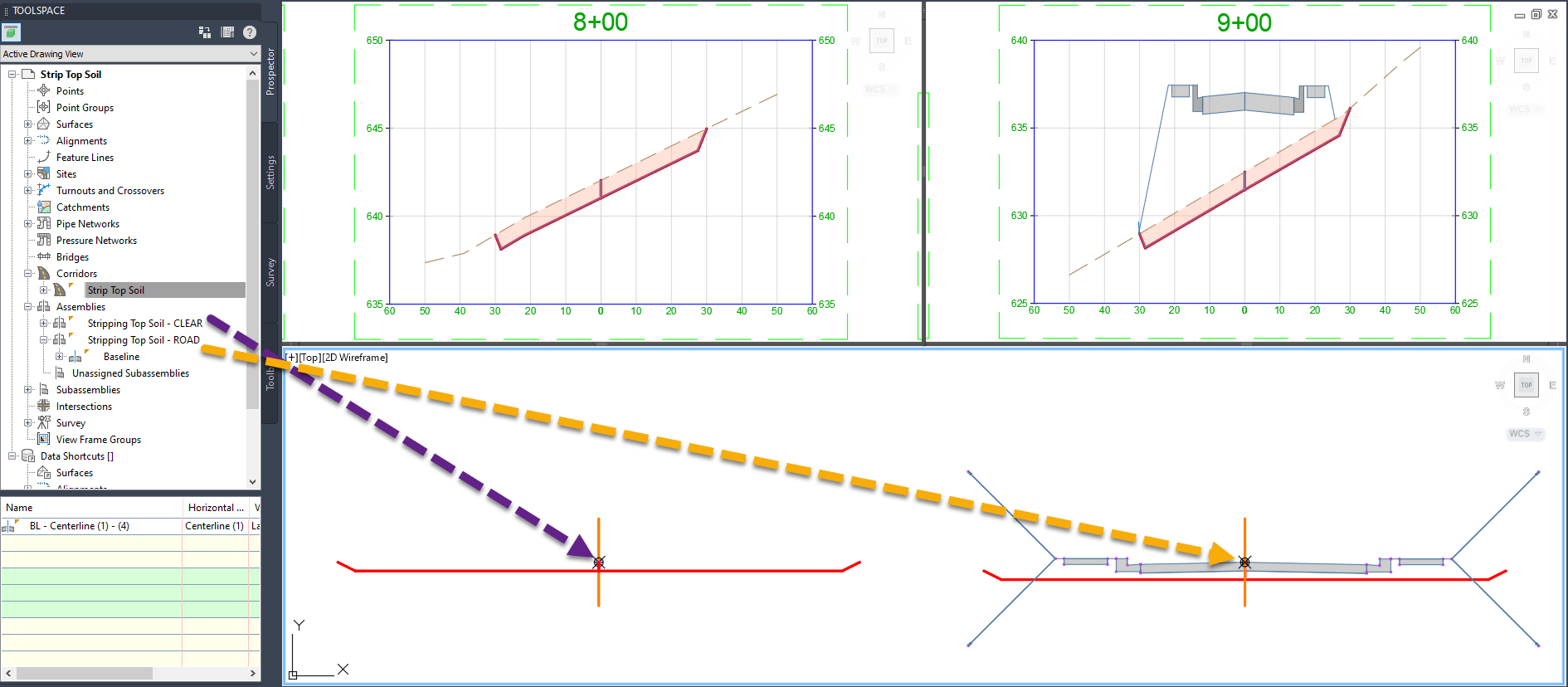
SCENARIO 1: CLEARING THE WAY AT A SPECIFIED WIDTH
First, the Stripping Top Soil subassembly will simply attach to the Assembly to the left and right. The subassembly is using the set distance (30’) to each side. 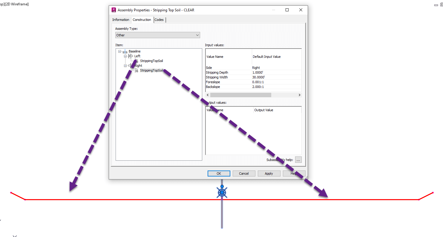
When the corridor is created and the surface set as a target, the subassembly will tie to the terrain. It does not matter if you use the Existing Grade (sta 11+50) or Finished Grade (sta 14+50) profiles. 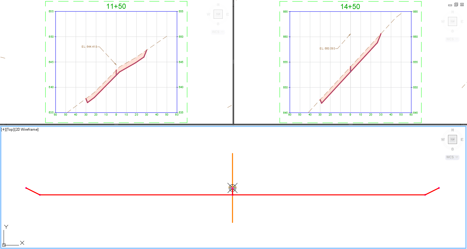
In this simple case, a buffer width zone (60’ total width) along the alignment path is being cleared to a stripping depth.
SCENARIO 2: ROADWAY SECTION AND STRIPPING
Next, the assembly section gets to be more complex roadway design. In the created roadway section, the Stripping Top Soil subassemblies are attached to the base Assembly. For a total of two Stripping subassemblies, attaching to the left and right sides. 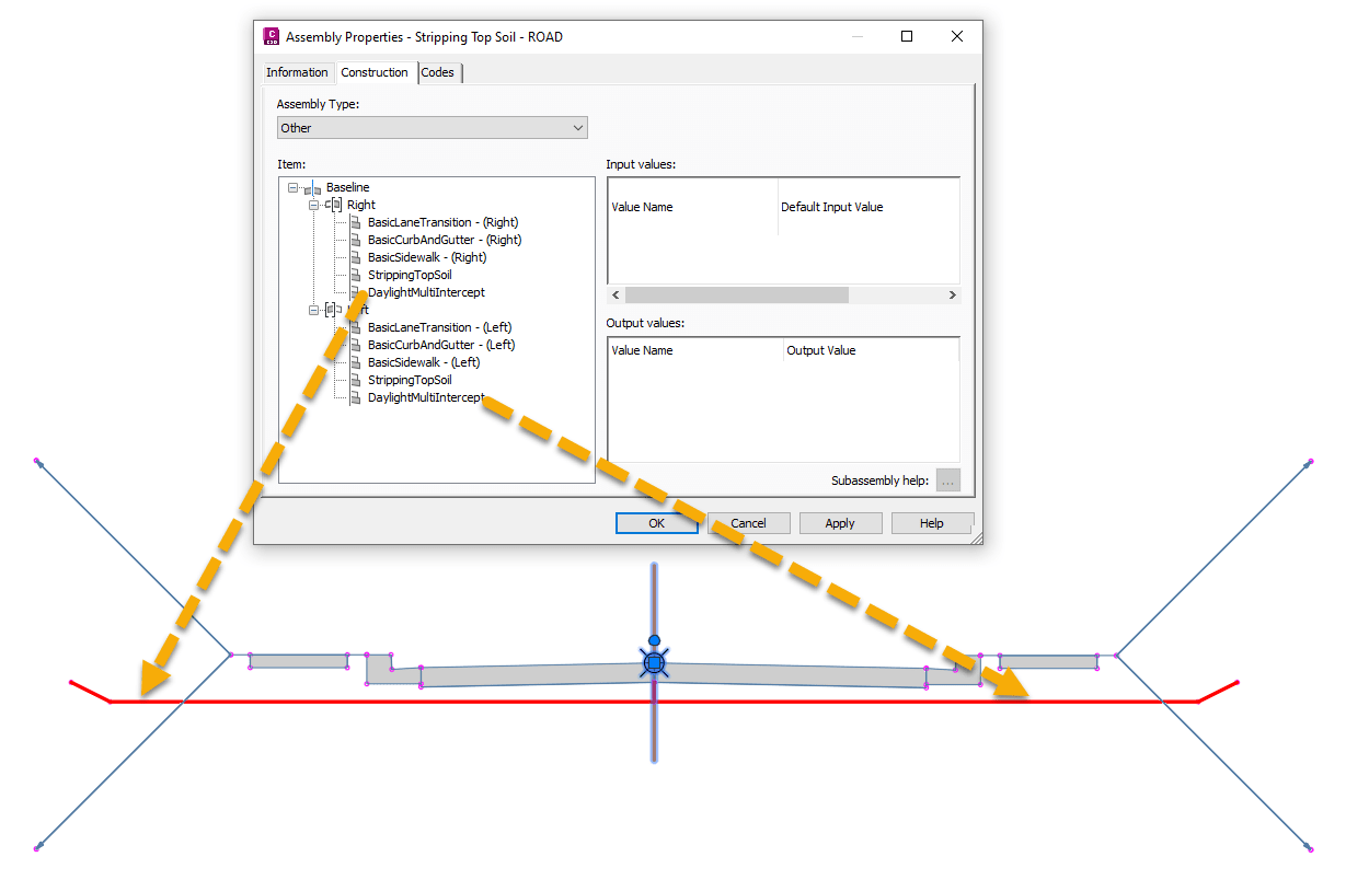
When the corridor is built and the existing surface (EG) set as a target, the subassembly will tie to the terrain. The stripping width distance is static in every view. 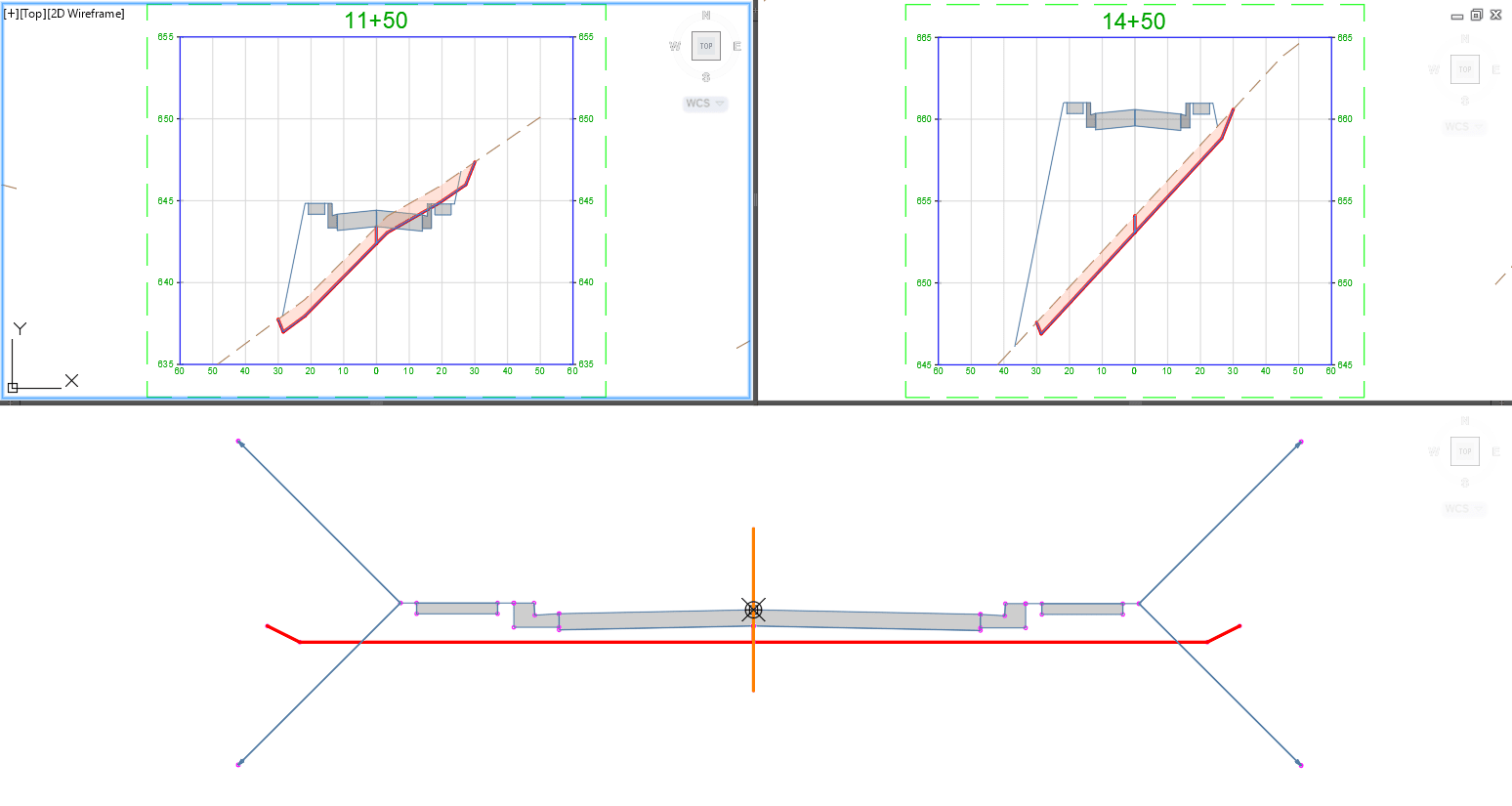
This example highlights how the terrain location attachment is the same from section to section. And ONLY calculating the stripping of soil to the set depth and NOT calculating TOTAL excavation values.
Both scenarios above include the display of Computed Materials. The analysis of data created a highlight of the “cut” from the stripping subassembly shaded in red. This requires creating a Corridor, Design Surface, Sample Lines, and Styles to show the area of sectional materials.
IMAGINiT can help you learn more about how to work with set up and configuration. Please visit our web site and see our other posts on using subassemblies or contact us.
About the Author
More Content by Leo Lavayen


