
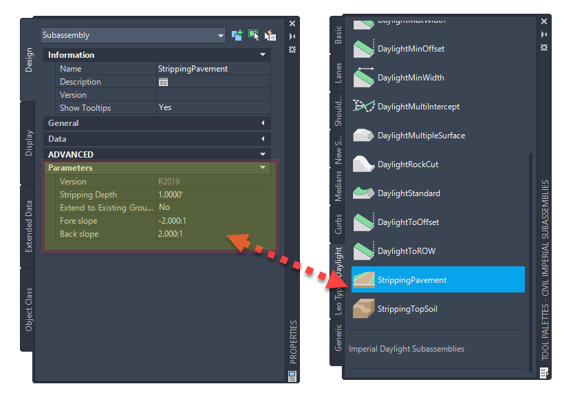
This post will review the Daylight subassembly called Stripping Pavement. This subassembly is used to specify the existing top layer stripping to a specified depth. Details can be found directly from the Autodesk HELP file.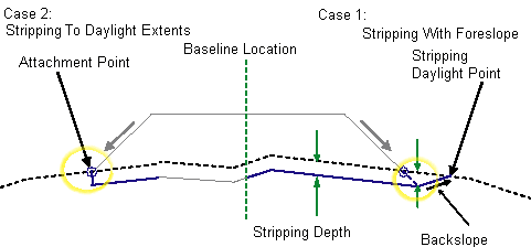
From the help file we learn that “This subassembly is used to specify the existing top layer stripping to a specified depth”. Built in with a two case options for attaching to terrain: Stripping to Daylight Extents or Stripping with Foresloipe). The Subassembly has been configured the following way for this example:
We will be exploring two design scenarios and behaviors:
• Simple Generic Width
• Roadway Section with Daylight 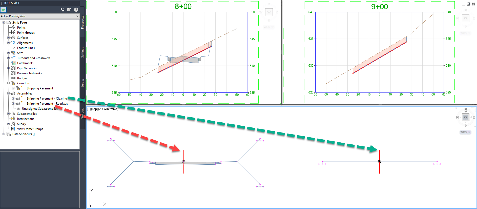
SCENARIO 1: CLEARING THE WAY AT A SPECIFIED WIDTH
In the First case the Centerline will be use a Generic Link Width and Slope subassembly to the Left and Right to a set distance (25’). Attached to the Generic Links will be the Stripping Pavement subassembly on both sides. 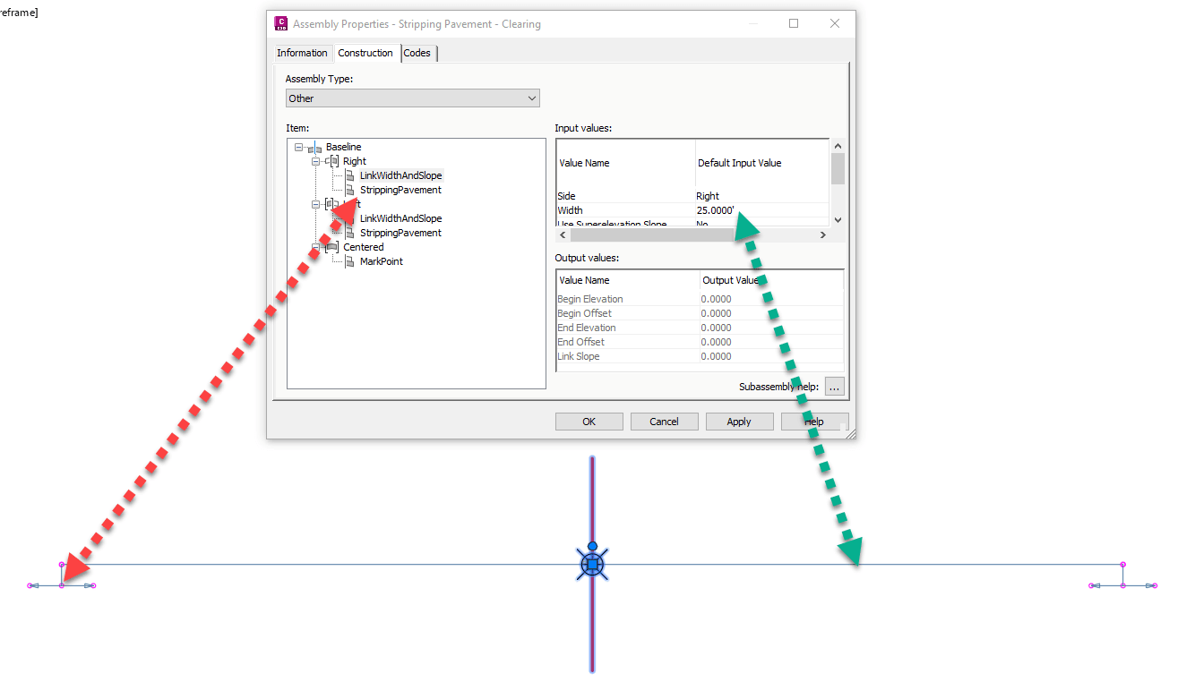
When the corridor is created and the surface set as a target, the subassembly will tie to the terrain, shown as a vertical cut section. It does not matter if you use the Existing Grade (sta 8+00) or Finished Grade (sta 9+00) profiles. If it hovers above or below the surface, it is just looking for a is a preset width and depth to offset to. 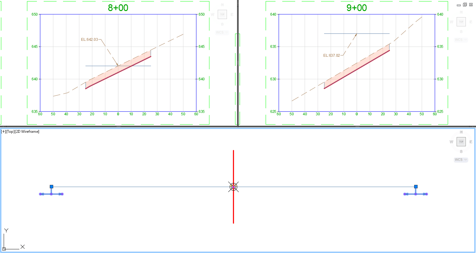
In this simple section layout, a buffer width zone (50’ total width) along the alignment path is being cleared at a stripping depth. The corridor element can be removed from the section view, only displayed here to show how the design elevation is not critical to establishing depth.
SCENARIO 2: ROADWAY SECTION WITH STRIPPING
Next, the assembly section gets to be more complex roadway design. In the created roadway section, the Stripping Pavement subassembly are attached to the outer most points. For a total of four Stripping subassemblies, attaching to the daylighting cut and fill subassemblies on the left and right sides. 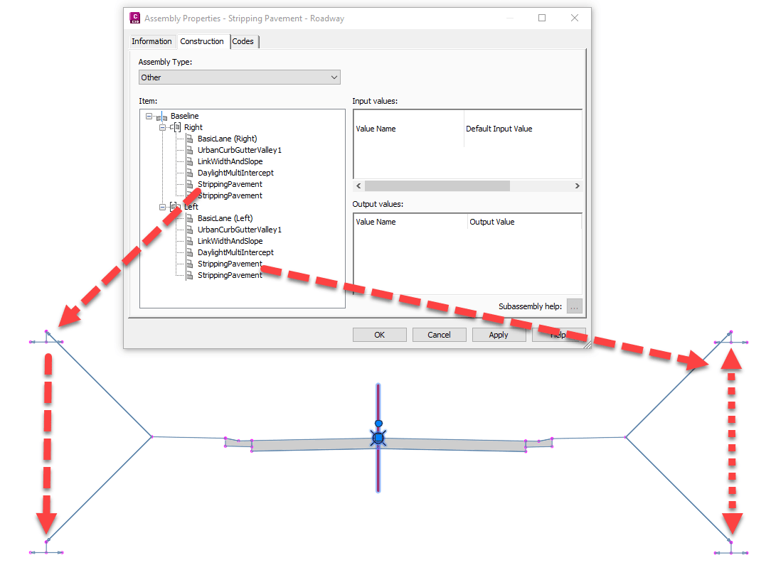
When the corridor is created and the existing surface (EG) set as a target, the subassembly will tie to the terrain. The stripping width will vary, as the location attachment shifts as the cut and fill slopes daylight to the surface. 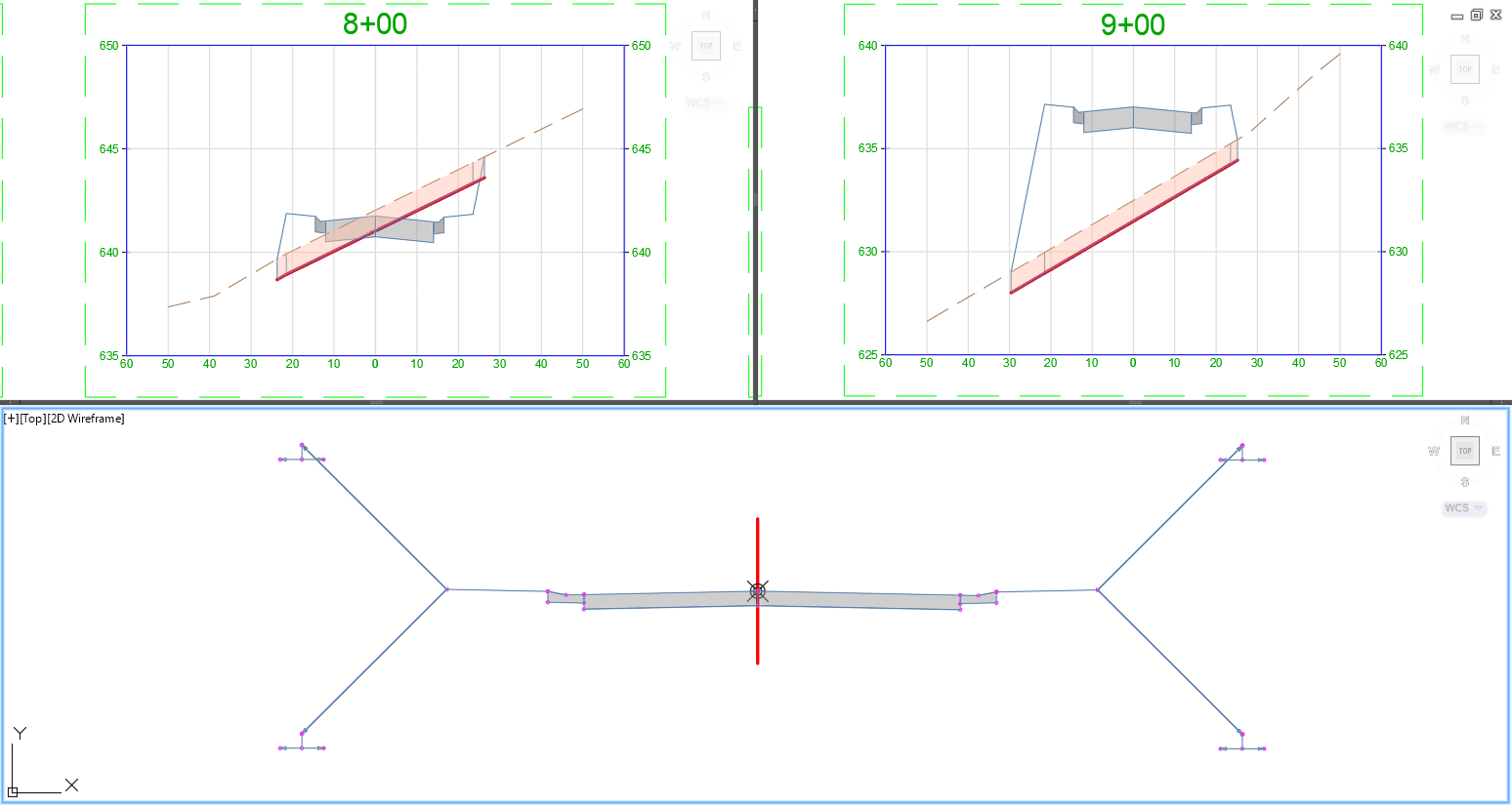
This example is ONLY calculating the stripping of soil to the set depth and NOT calculating TOTAL excavation values. Notice when the design dips below the Existing Grade (EG) surface, only the stripping depth is highlighted.
Both scenarios shown above include the display of Computed Materials. The analysis of data created a highlight of the “cut” from the stripping subassembly shown in red. This requires creating a Corridor, Design Surface, Sample Lines, and Styles to show the area of sectional materials.
IMAGINiT can help you learn more about how to work with subassemblies, calculate volumes and configuration. Please visit our web site to see our other posts on using subassemblies or contacts us.
About the Author
More Content by Leo Lavayen


