

Have you ever noticed that when you drag a Civil 3D label, the leader arrowhead sometimes attaches to the center of the marker and other times to its edge? This behavior isn't random—it's controlled by a few settings that are easy to overlook. 
The AutoCAD Properties palette, shows three options under the Annotation section → Leader Attachment Option selection:
• From Marker Style
• Point
• Markers Extents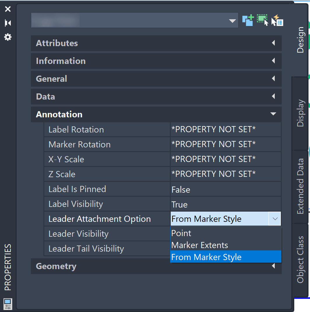
Understanding these settings allows you to choose the attachment method that best fits a project's annotation standards. This behavior is not limited to Point objects. Other Civil 3D labels, such as Surface Spot Elevation, Alignment Station Offset, and many other labels.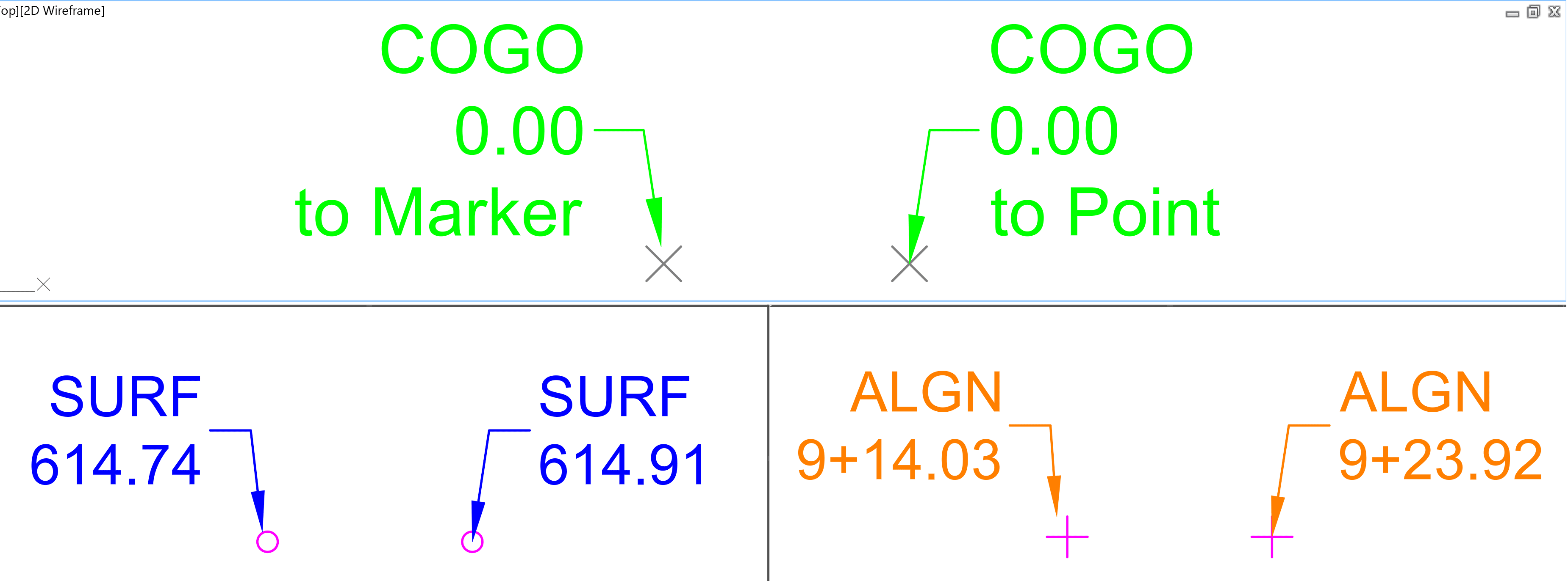
When he leader location behavior is set to marker style, the marker will need to be configured. From the Point Style dialog box → Summary tab → Marker category → Leader stops at marker selection: 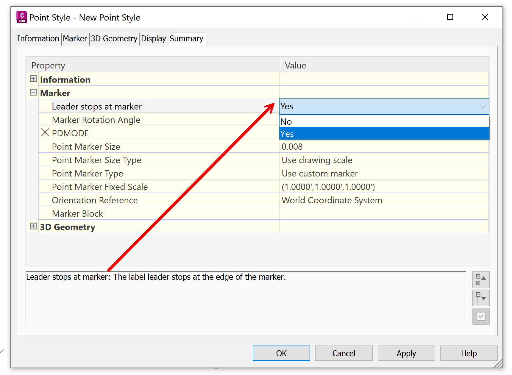
This setting establish a default leader attachment behavior for different point styles based on your organization's drafting standards. For example, lets focus on Point type data. The image below shows how the arrowhead position changes between different Civil 3D Point Styles: 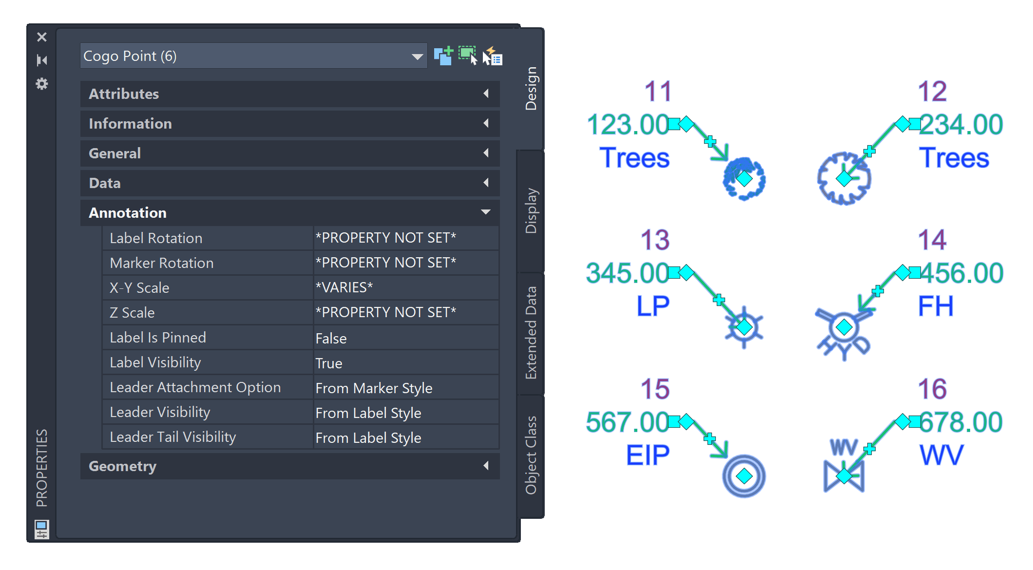
By understanding these leader attachment options, you can create cleaner, more consistent annotations and establish default behaviors that match your company's drafting standards.
About the Author
More Content by Leo Lavayen


