
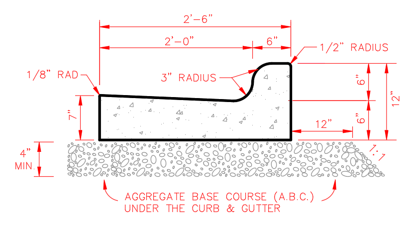
The goal is to create an assembly with a curb section that matches a standard detail below, base course with a sloped extension:
THE ISSUE:
While reviewing the four Uban Curb Gutter subassemblies, they all have a parameter for a “Subbase Extension” (1.00’ by default). Unfortunately, it is created with a vertical drop and NO option to create a slope: 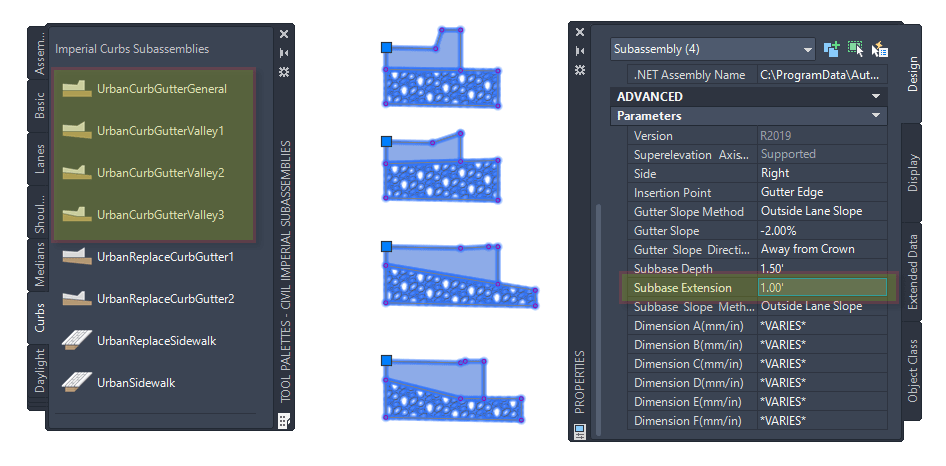
THE SOLUTION:
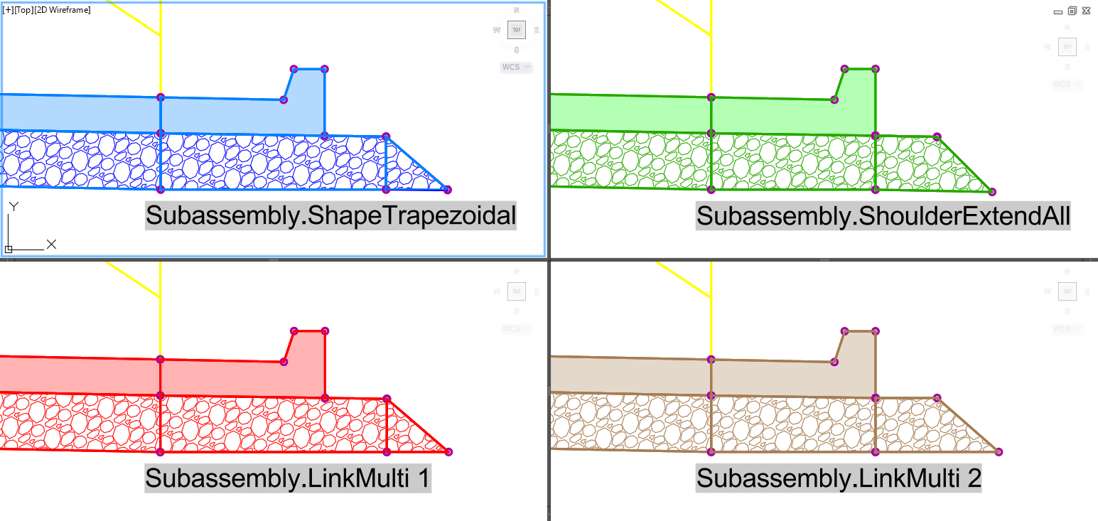
Here an additional subassembly will be added to create the sloped wedge. In this example, we will use a few out of the box subassemblies to expore some options to match the needed standard detail:
• Shape Trapezoidal (blue)
• Shoulder Extend All (green)
• Link Multi (red and brown)
Option 1: Shape Trapezoidal
The first subassembly explored here: Shape Trapezoidal is found on the Basic tab of the Tool Palettes. The Curb subassembly extensions is set to 1.00. The depth and slope parameters have been set to match the Curb and the Shape Code has been set to Subbase. 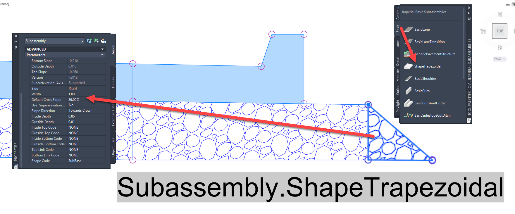
Option 2: Shoulder Extend All
The second subassembly explored here; Shoulder Extend All is found on the Shoulders tab of the Tool Palettes. The Curb extensions is set to 0.00. The depth and slope parameters have been set to match the Curb and the Shape Code defaults to Subbase. 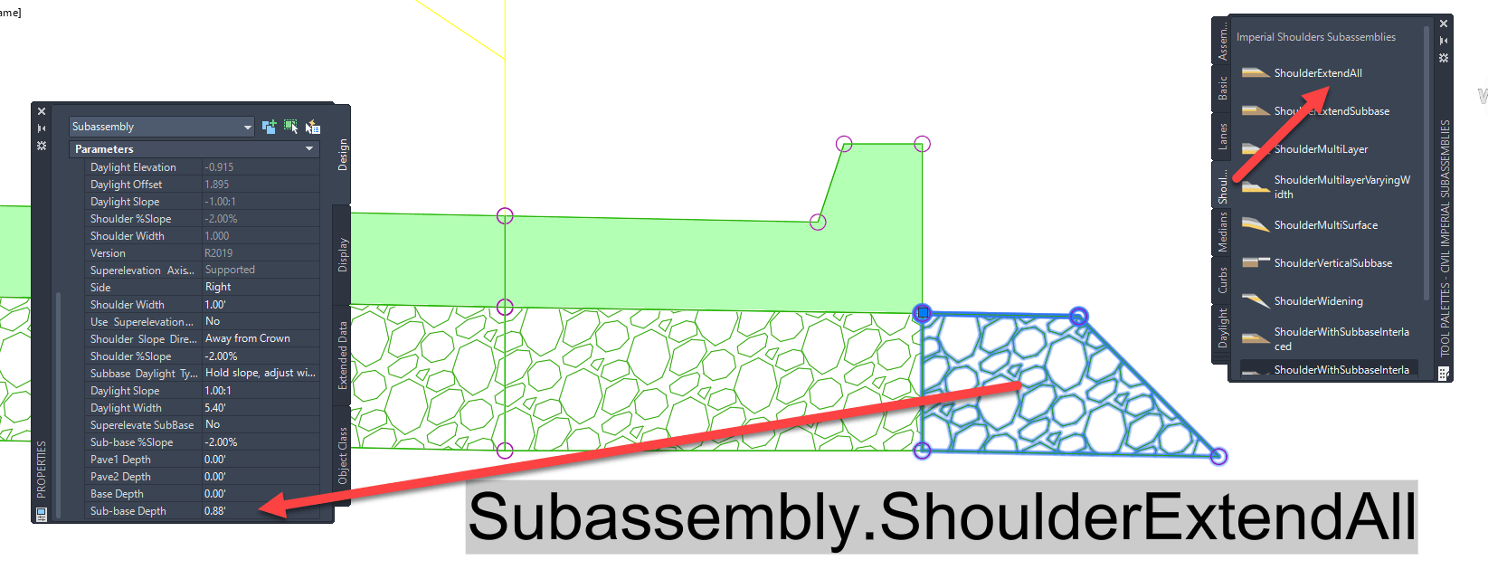
Option 3: Link Multi (example 1)
The third subassembly explored here: Link Multi is found on the Generic tab of the Tool Palettes. The Curb subassembly extensions is set to 1.00. The total number or links is set to 3 and depth and slope parameters have been set to match the Curb and the Shape Code has been set to Subbase. 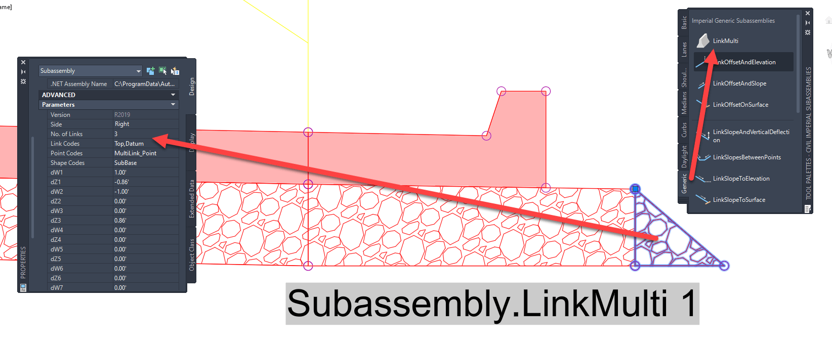
Option 4: Link Multi (example 2)
Here again the Link Multi subassembly is used, found on the Generic tab of the Tool Palettes. The Curb subassembly extensions is set to 0.00. The total number or links is set to 4 and depth and slope parameters have been set to match the Curb and the Shape Code has been set to Subbase.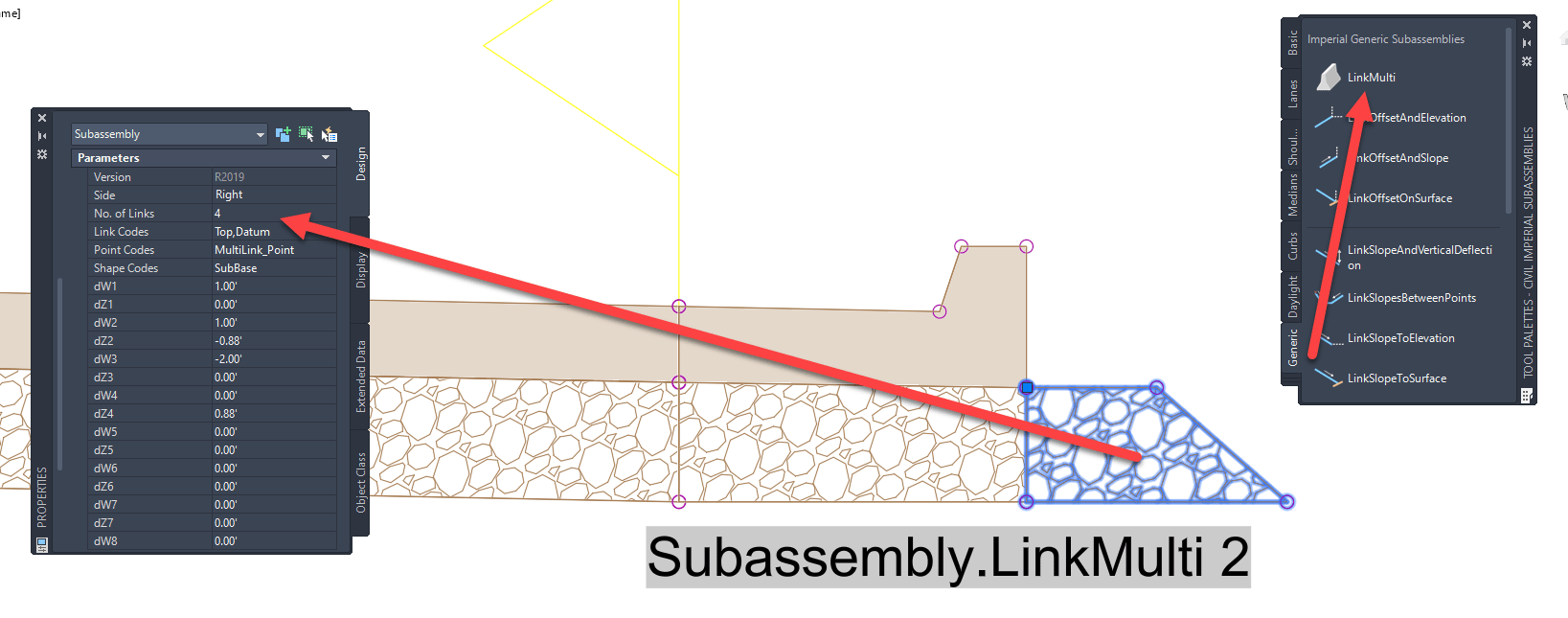 NOTE:
NOTE:
All of the created sloped wedge elements are additions to the Curb with the same underlying shape code. This causes a line to be drawn in between the subbase, while maintaining the same gravel pattern.
I hope this post has taught you some options on how to create a wedge subassembly to work with a Curb and Gutter. Another option is to create Custom Curb subassembly for Civil 3D. If you have questions on how to use default subassemblies or have a need to create custom ones, IMAGINiT can assist you with that.
About the Author
More Content by Leo Lavayen


