

When designing corridors with two parallel alignments separated by a gap, using a single baseline can produce unexpected section slope values. This behavior is especially noticeable when comparing traditional Assemblies vs Assembly Offsets design. 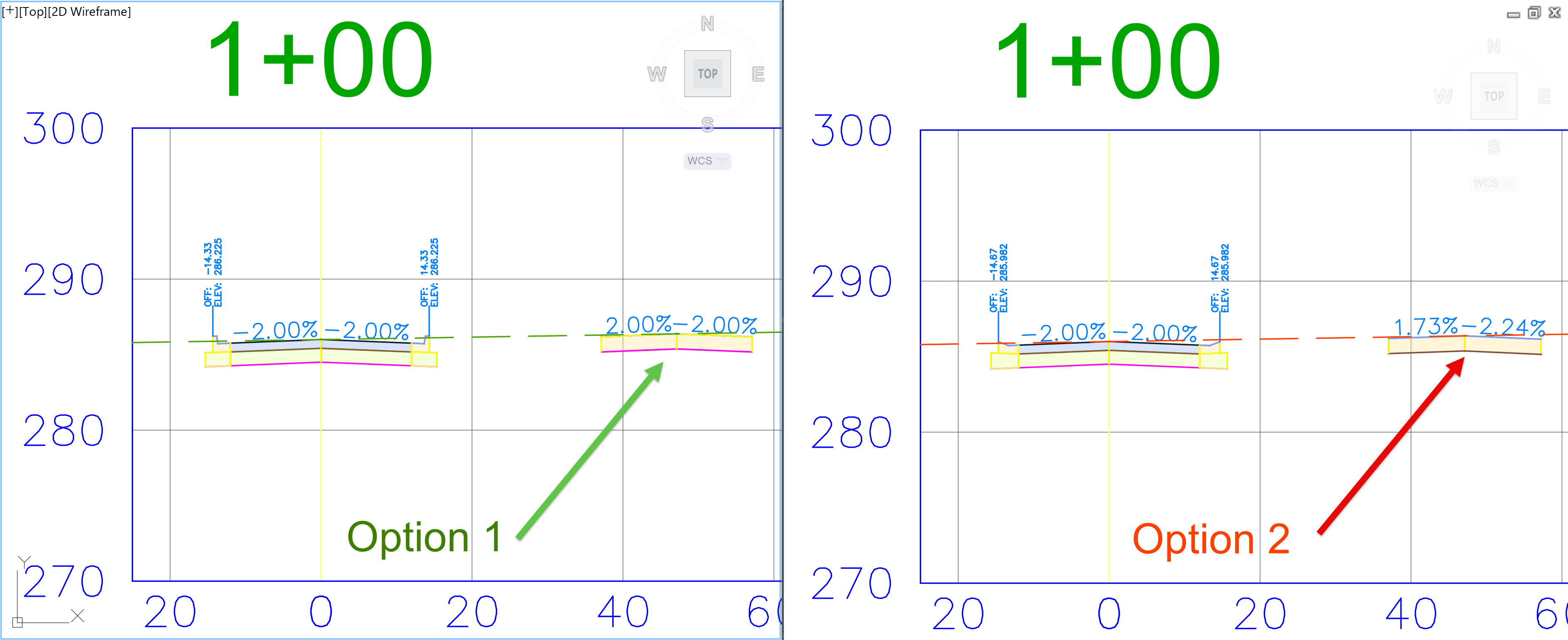
Option 1: classic Assembly Design
To create the gap between the roadways within the assembly, the Link Width and Slope subassembly is used. Found on the Generic tab of the Civil 3D Subassemblies Tool Palette. 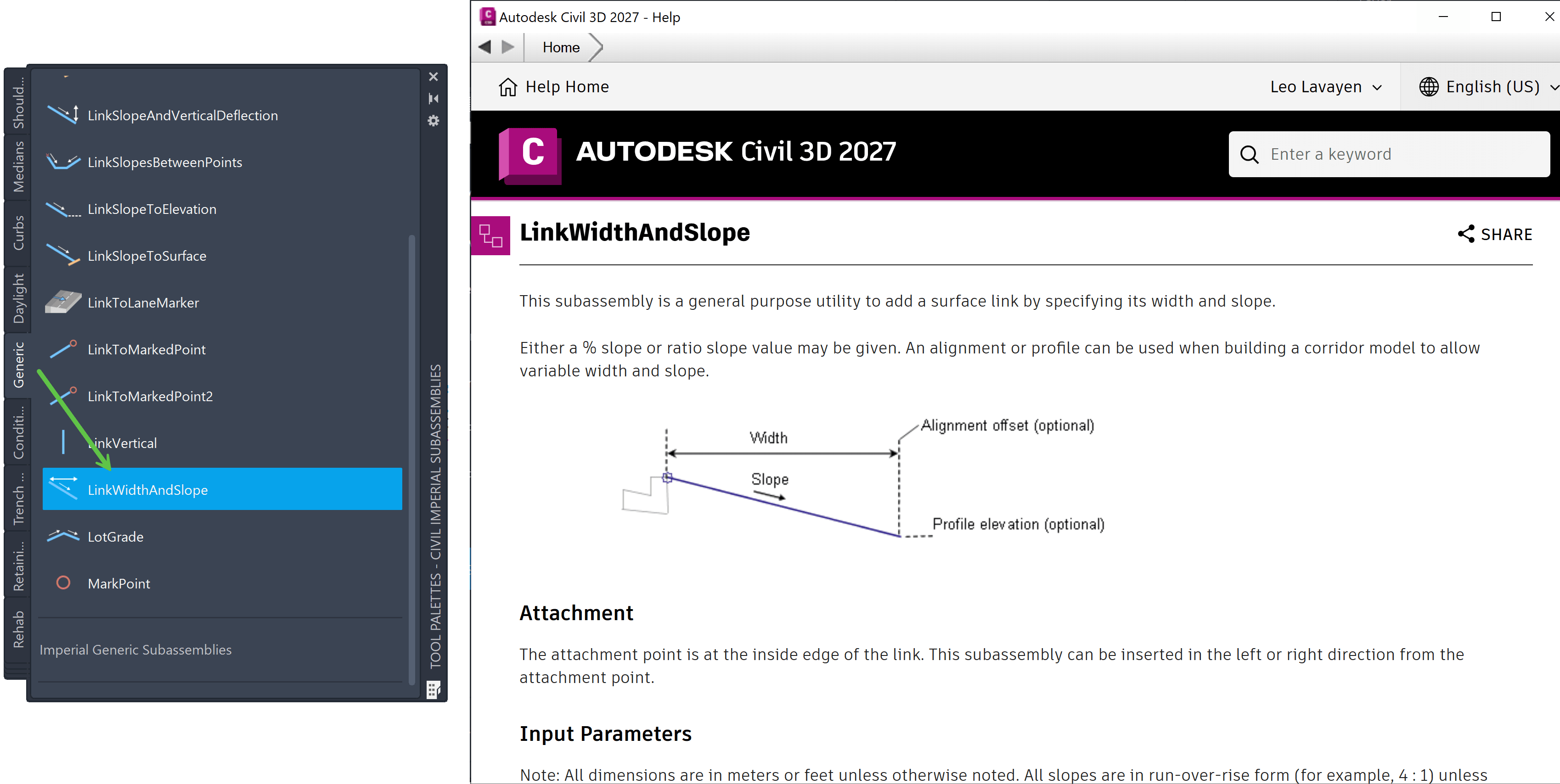
Once the link is added, attach the required subassemblies to the Link Width and Slope subassembly. In this example a simple roadway is spaced and all pavement sections are set to 2.00% slope. 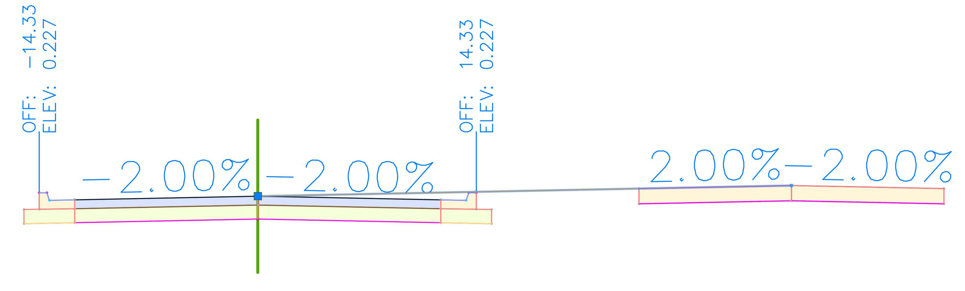
In the Construction for the built Assembly, the Link Width and Slope (W:30’) is attached to the Baseline towards the Right side. 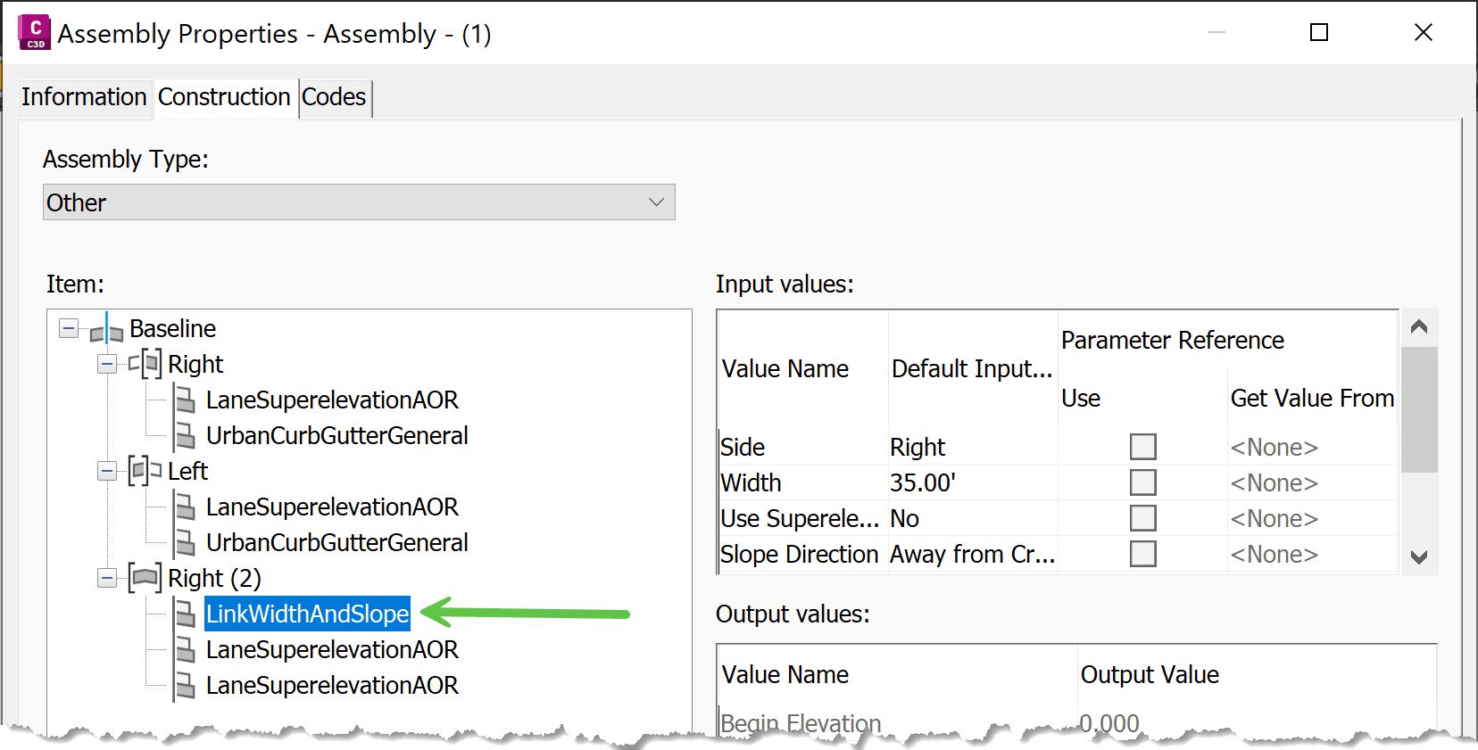
When building Corridors, this method requires assigning targets to the Link Width and Slope subassembly. Remember to select BOTH the Offset (horizontal) and Profile (vertical) targets. 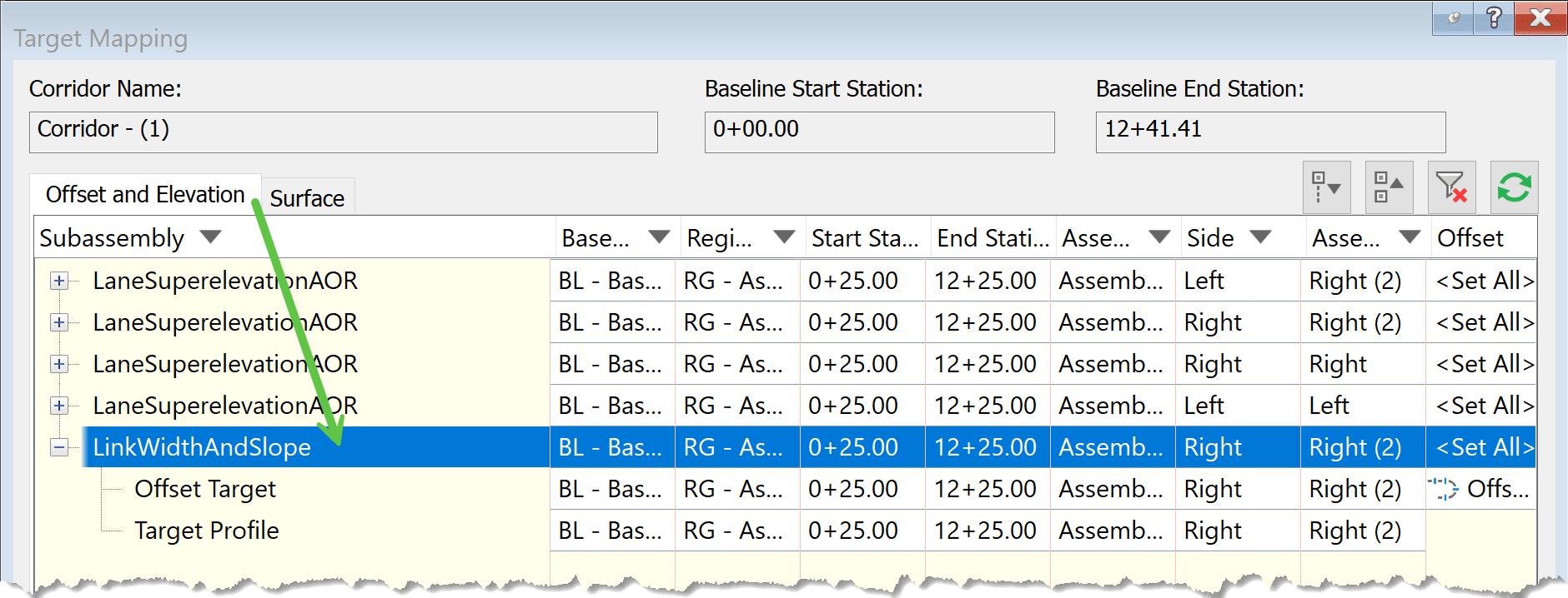
This creates a design that is perpendicular to the main base line alignment all the way out to the offset. 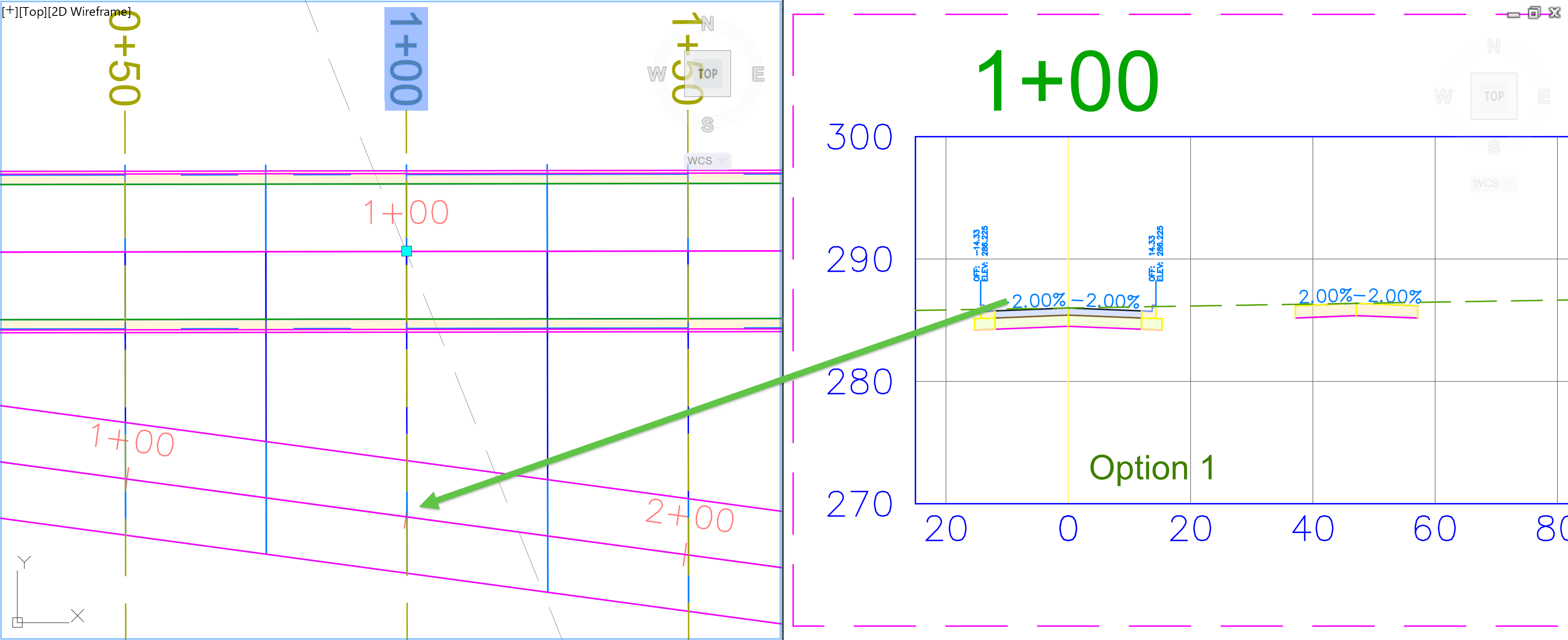
Notice that a 2.00% slope is displayed from the baseline roadway to the offset roadway.
Option 2: using Assembly Offset
To create the gap between the roadways, an Offset is created. Select the Assembly on screen > from Contextual Ribbon → Assembly: “Name” → Modify Assembly panel → Add Offset button 
Once the Assembly Offset is add, attach the roadway subassemblies to the offset baseline. Similar to the first option, the roadway is spaced and all pavement sections are set to 2.00% slope. 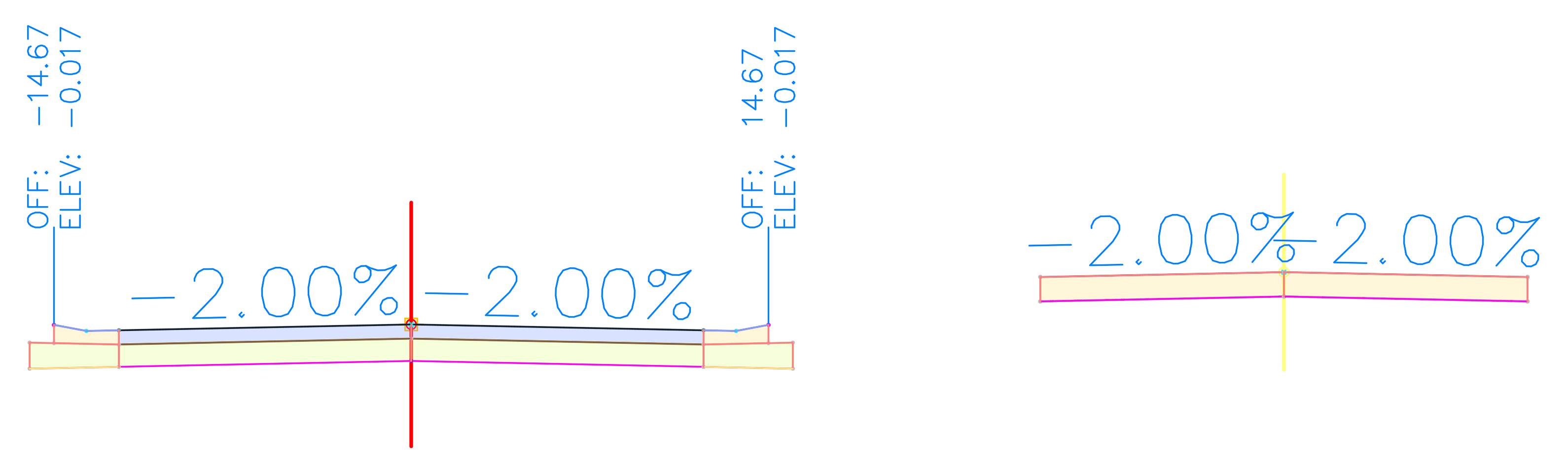
In the Construction tab of built Assembly, shows the offset is attached to the baseline and maintains independent Left and Right sides. 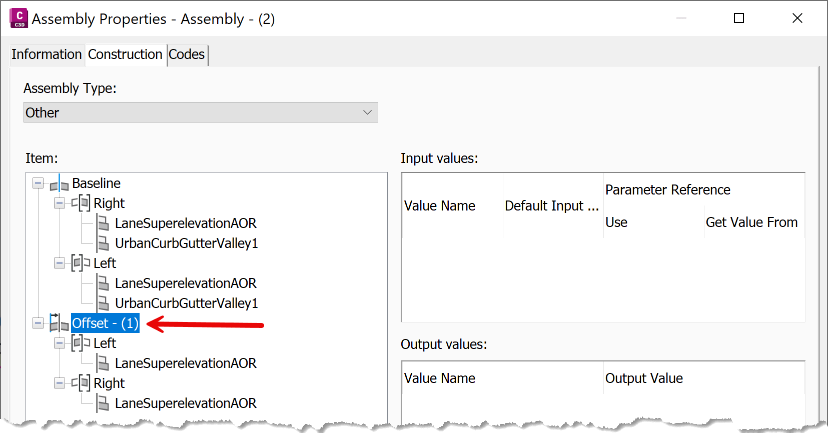
Unlike the first method, no Link Width and Slope targets are required. Here, directly from the Parameters tab of the Corridor, the Horizontal and Vertical Baselines can be selected.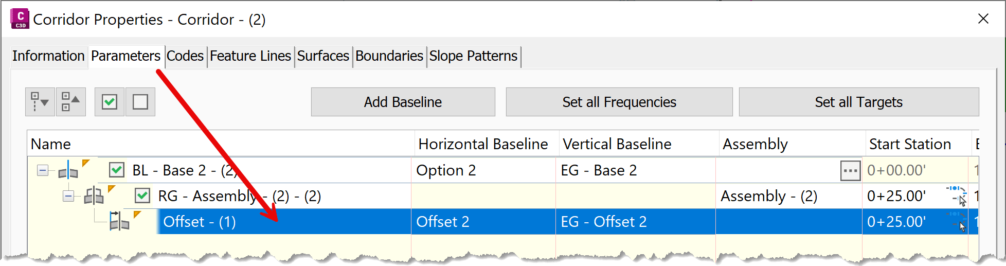
Unlike the first method, no Link Width and Slope targets are required. Here, directly from the Parameters tab of the Corridor, the Horizontal and Vertical Baselines can be selected.
This creates a design that is perpendicular to the main base line alignment and perpendicular to the offset design. 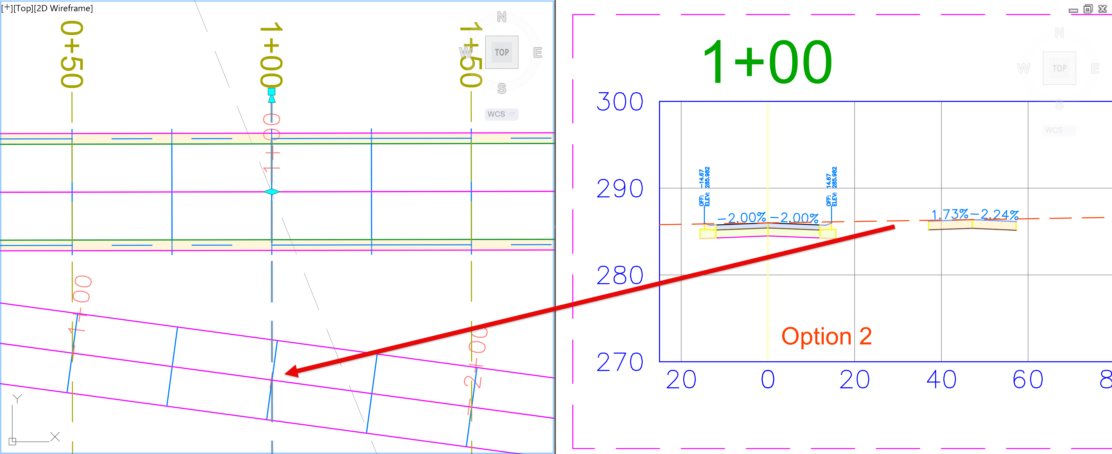
Notice that the displayed 2.00% slope applies only to the baseline roadway.
Because the subassemblies rotate so they remain perpendicular to the Assembly Offset alignment, the apparent slope values displayed in section views can differ from what users expect. The design itself is correct, but the reported section slopes reflect the rotated orientation.
Because the subassemblies rotate so they remain perpendicular to the Assembly Offset alignment, the apparent slope values displayed in section views can differ from what users expect. The design itself is correct, but the reported section slopes reflect the rotated orientation.
Understanding how Civil 3D "twists" subassemblies when using Assembly Offsets is important when reviewing corridor section labels, evaluating displayed slopes, and generating corridor surfaces.
Although both design approaches can produce the intended geometry, the reported section slopes may differ because they are measured relative to different baselines. Recognizing this distinction helps avoid confusion during design review and construction documentation.
This topic builds on a previous post discussing multiple-baseline corridors and why section slope values vary depending on the selected baseline:
https://resources.imaginit.com/civil-solutions-blog/c3d-multiple-baseline-corridor-and-section-slope-values
About the Author
More Content by Leo Lavayen


