
While labeling Civil 3D objects the need to add a mark at the location where label is placed might come up. There are two options: create a label with a Block component or pair the label with a generic Marker style.
Here we will explore four Civil 3D object labels and how “x” can mark the spot:
• Alignment: Station Offset
• Surface: Spot Elevation
• Profile View: Station Elevation
• Section View: Offset Elevation 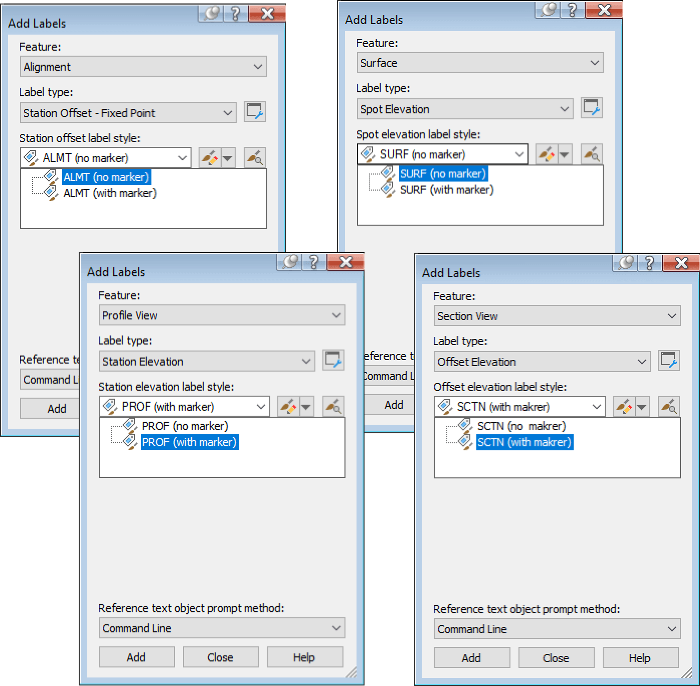
The configuration is very similar across all objects. The labels are very similar in the eight labels and both versions: no marker vs with marker. 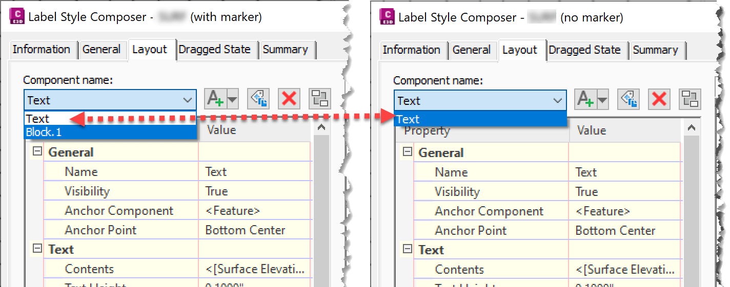
The main difference in behavior can be appreciated when label is dragged from its default location, and what happens to the “X” maker. 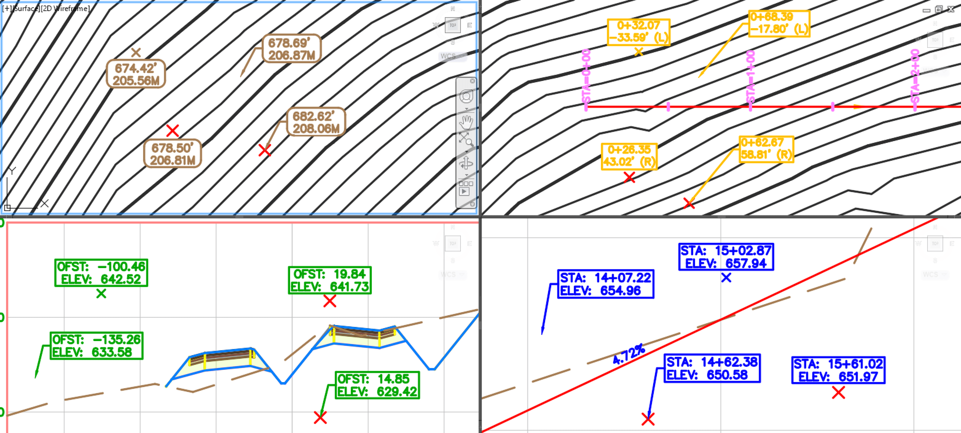
All the label style (with and without marker) have been configured similarly, let’s review the configuration and behavior differences in the styles.
Label styles “with marker” embedded in to style
When using these type of configured annotations, the styles “with maker” are selected and the Maker styles set to <none>:
The configured labels have two components:
• Text: that display data
• Block.1: that calls for an “x” block 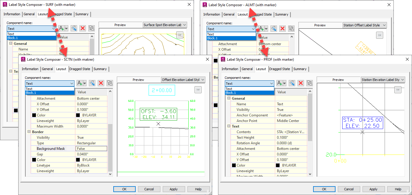
For all the configured labels, the Dragged State Components selection are set to: Staked Text 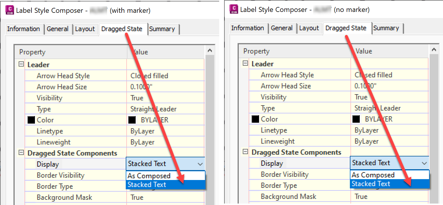
This setting crucial in behavior, as the Staked Text option will cause the marker to disappear when dragged in the “with marker” styles. 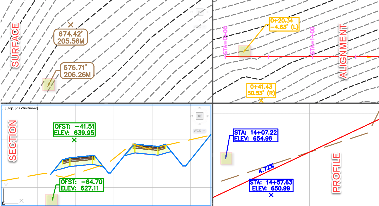
For more insight on how the Dragged State settings works, visit the Civil 3D help file.
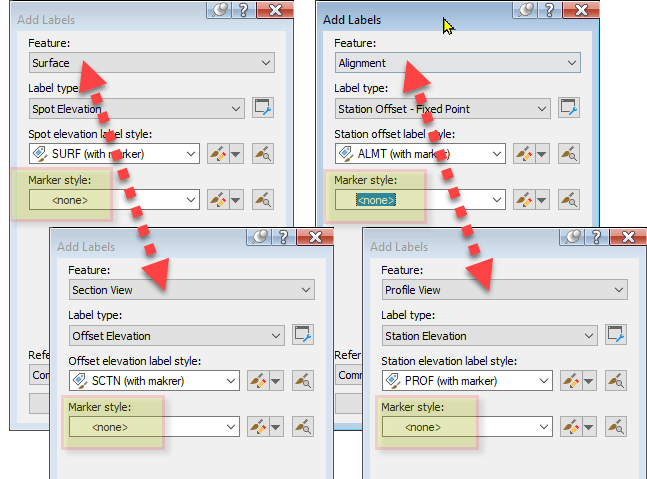
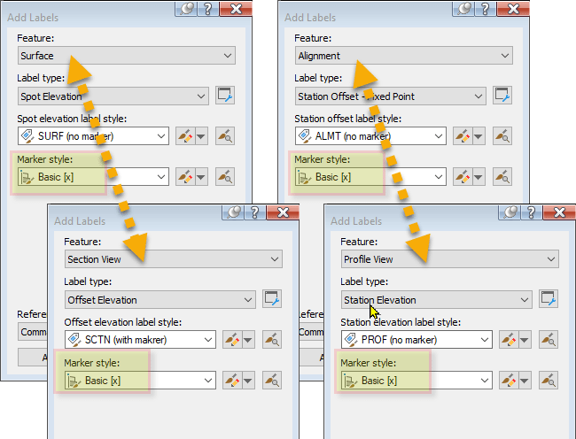
Labels “no marker” paired with generic Marker
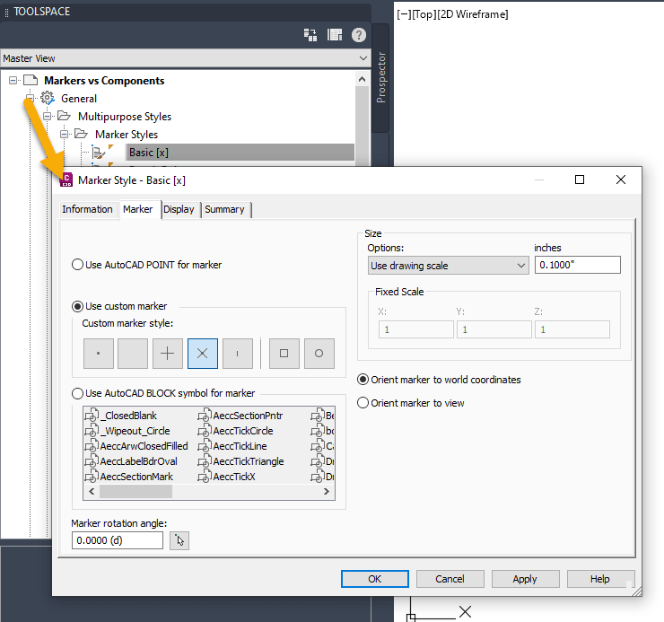
When creating using these types of configured annotations, the styles “no maker” are paried with the configured Basic [x] Maker style:
The configured labels has a single component: Text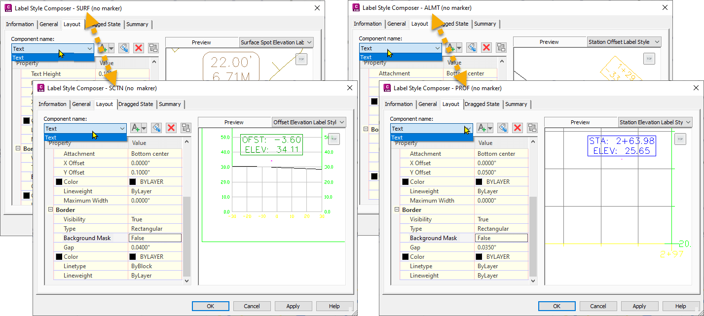
Again, here the Dragged State Components is set to “Staked Text”. As the Marker is a separate additional element it will remain: 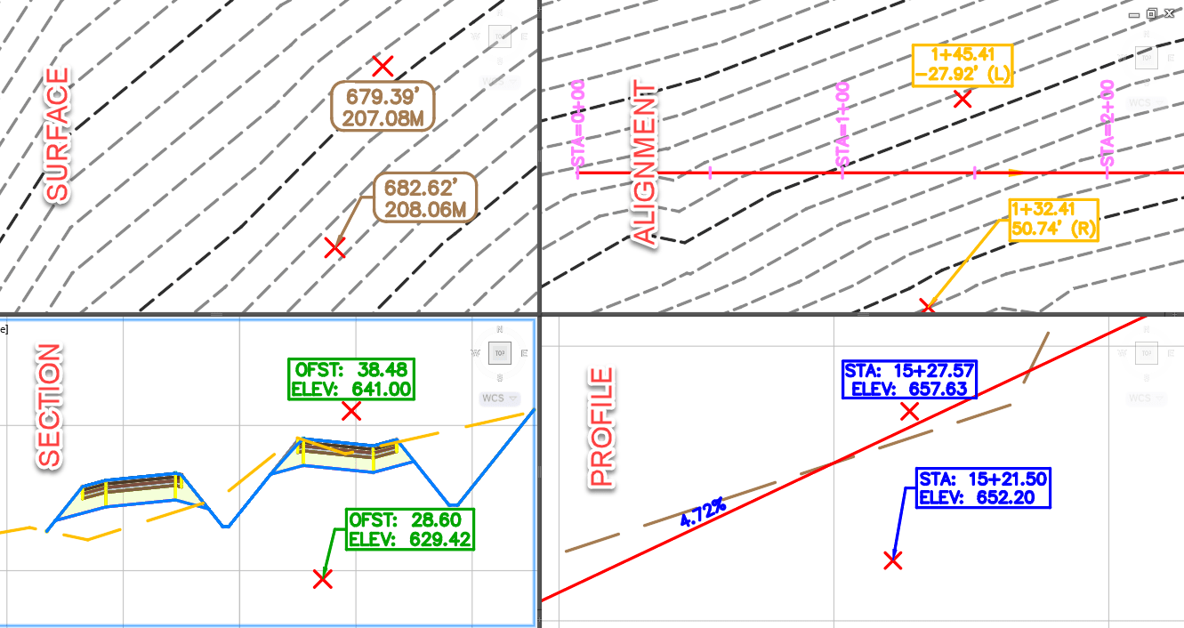
The configuration for the used marker is found the General category > Multipurpose Styles > Marker Styles (Not in each of the individual object categories).
Hope you found this write up helpfull. If you would like to test the configuration, download the drawing file.
If you enjoyed this post, visit our IMAGINiT support page for more content like this.
About the Author
More Content by Leo Lavayen


