
Welcome to the second of four blog posts focusing on common Survey issues and how they are addressed in Civil 3D. In today’s blog I will continue the lesson on important settings in Civil 3D for converting International Foot to Survey Foot.
But first…what is Latitude and Longitude?
Latitude and Longitude is a grid system used to pinpoint locations on our planet.
Latitude lines run parallel to the equator and measure the north or south position. Latitude lines, also known as parallels, range from 0° at the equator to 90° north and 90° south at the poles.
Longitude lines measure the east or west position and range from 0° at the Prime Meridian to 180° east or 180° west. The Prime Meridian passes through Greenwich, an area in the south-east of London, England. Longitude lines, also known as meridians, run north and south along the planet and converge at the poles. Meridians are not parallel, hence the need for map projection, but that is a lesson for another day.
The origin, where 0 degrees longitude and 0 degrees latitude intersect, is located in the middle of the Atlantic Ocean, specifically in the Gulf of Guinea, approximately 370 miles off the coast of West Africa.
In part one of the September Surveying Series we learned that the NAD83 SPCS is based on meters. In order to convert latitude and longitude to meters, multiply the degrees of separation of longitude and latitude by 111,139 to get the corresponding linear distances in meters.
The NOAA website has an excellent conversion tool on their website. NGS Coordinate Conversion and Transformation Tool (NCAT)

LandXML settings – International Foot vs. U.S. Survey Foot
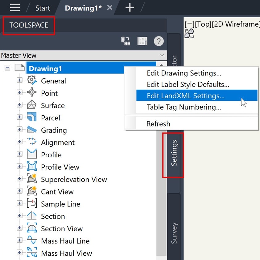
This should be done in your company template for project consistency. Right click on the active drawing name listed at the top of the Toolspace Settings Tab and select Edit LandXML Settings.
Import Tab: expand Surface Import Settings. Convert Survey Ft to International Ft.

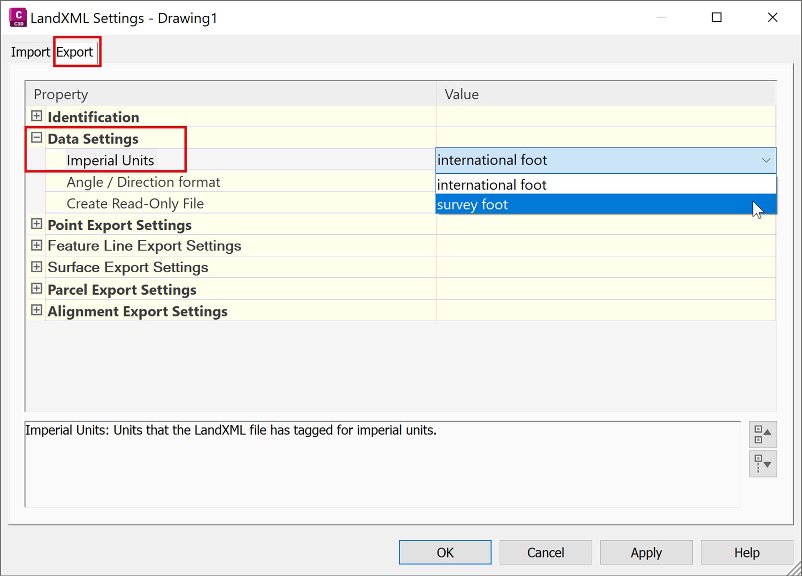
Export Tab: expand Data Settings. Imperial Units.
Next week we will explore some tips and tricks when using the Traverse Editor.
About the Author
Follow on Linkedin More Content by Dana Rice


