
Welcome to the first of four blog posts focusing on common Survey issues and how they are addressed in Civil 3D. In today’s blog I will discuss International Foot vs. Survey Foot and where to find the Civil 3D settings for conversion.
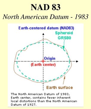
Let us learn a little background information before we get into the numerical differences. The U.S. Survey Foot was used by the National Geodetic Survey (NGS) to establish the State Plane Coordinates published in the North American Datum of 1927 (NAD 27).
NAD 27 uses U.S. Survey Foot.
In 1986 the federal government began moving towards international consistency in terms of units of measure. A part of that effort was the release of the North American Datum of 1983 (NAD 83), which forms the foundation for the State Plane Coordinate system (SPCS).
NAD83 uses International Foot and the SPCS is based on meters.
A U.S. survey foot is expressed as a fraction: 1200/3937 meters.
An international foot is expressed as a decimal: exactly 0.3048 meters.
That is a difference of only one one-hundredth of a foot per mile. This difference has a minimal impact when using a local datum, however, when you are working in a coordinate system the discrepancy can become exponentially significant.
For example, let us convert the latitude and longitude of Charlotte, North Carolina to U.S. Survey Foot and International Foot:
35° 13’ 37.5060” N (165,410.337 m)
80° 50’ 35.2460” W (441,842.96 m)
U.S. Survey Foot:
N: 165,410.337 * (3937/1200) = 542,683.747
W: 441,842.96 * (3937/1200) = 1,449,613.111
International Foot:
N: 165,410.337 / 0.3048 = 542,684.832
W: 441,842.96 / 0.3048 = 1,449,616.010
I have highlighted the differences in bold
That is a 1.085’ difference in the Northing and 2.899’ difference in the Easting!
Because of this difference, it is imperative to know your drawing settings in Civil 3D.
These settings can should be addressed in your company template.
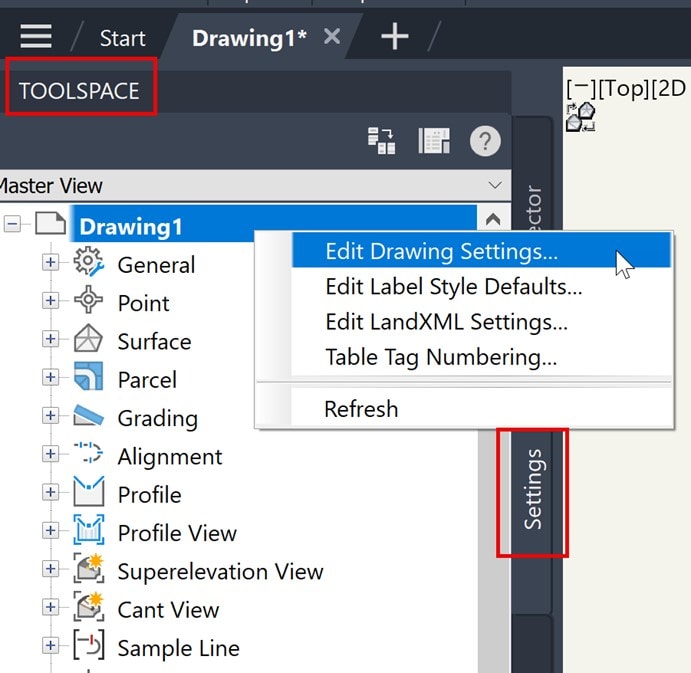
- Right click on the active drawing name listed at the top of the Toolspace Settings Tab.
- Select Edit Drawing Settings.
3. Change the Imperial Conversion to either U.S. Survey Foot or International Foot in the Drawing Settings dialog box Units and Zone tab.
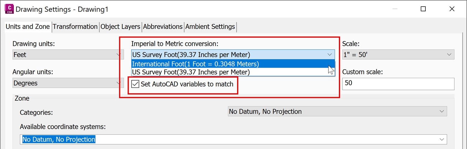
The ‘Set AutoCAD variables to match’ setting will synchronize AUNITS, DIMAUNIT, INSUNITS, and MEASUREMENT AutoCAD system variables.
4. Set the SPCS in the Drawing Settings dialog box. 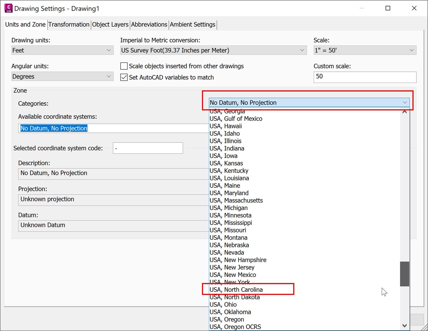
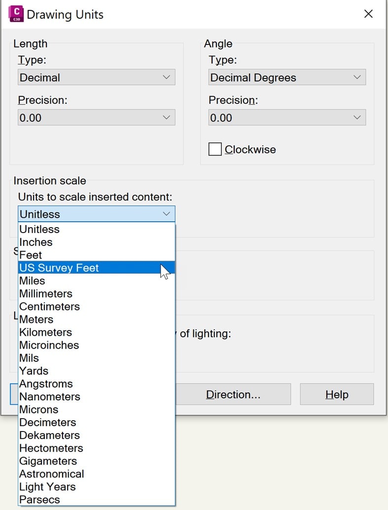
5. Type UNITS in the command line and verify the drawings insertion scale.
Feet is International Foot.
If you insert a block or a drawing that is created with units that are different from the units used in the current drawing, the insertion scale value corrects the mismatch. If you do not want the block or drawing to be scaled, specify Unitless.
Controlling the settings in these two locations is a good start for your company template. Next week we will explore settings for LandXML creation.
About the Author
Follow on Linkedin More Content by Dana Rice


