
While creating Assemblies in Civil 3D, it is possible to duplicate subassemblies during layout. The image below shows the details in the Construction tab of the Assembly Properties dialog box. As shown the Right side has multiple “Right Lane” subassemblies attached: 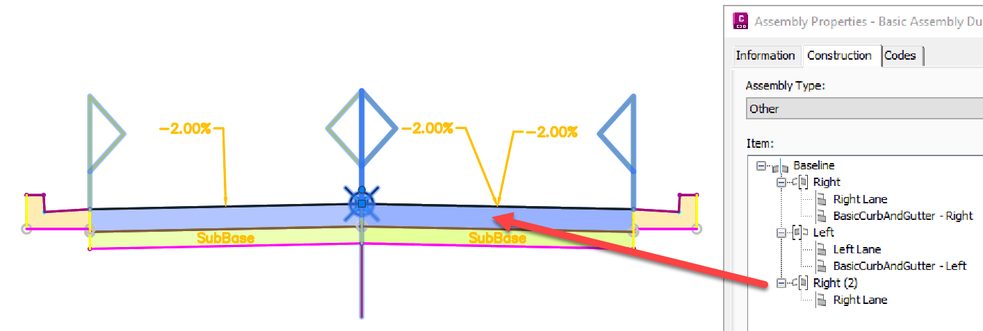
As an example, annotations have been dragged and note how there are two slope (-2.00%) labels on the right side. Looking closer, it appears to be slightly darker as objects are stacked. Let’s explore how this duplicate pavement might affect design output.
ISSUE: DUPLICATE DISPLAY
When adding Corridrors to Section Views, the duplication might reveal itself as a darker shade. If plotted (electronic or physical) the duplicate objects could show as thicker or heavier: 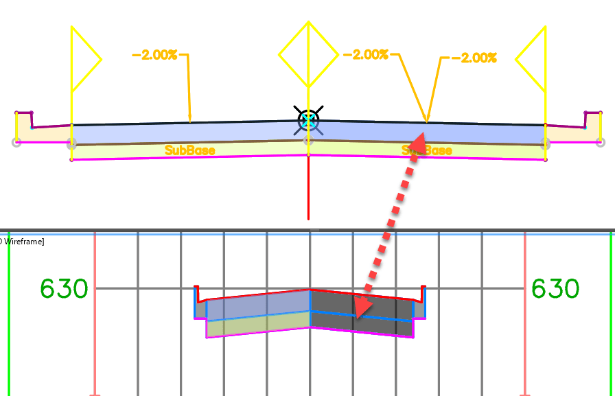
ISSUE: EXAGGERATED CORRIDOR VOLUMES
If volumes are calculated the duplicated times would be counted as many times as they appear. When running the Compute Materials command, the Edit Material List dialog box will simply call for the defined “Structures” corridor elements. No obvious duplication will be seen here.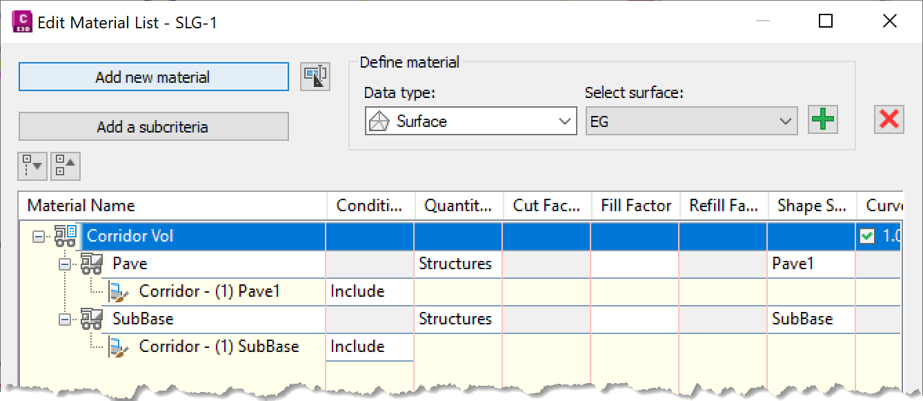
As the Lanes have the same “Pave” and “SubBase” codes assigned to them, there will be no way to separating the volume analysis. Typically, there is no need to differentiate indvidual elements or Left and Right sides. Resulting are typically seen as a singular total volume.
SOLUTION: REMOVE DUPLICATED SUBASSEMBLIES
Below the duplicated Lane subassembly that is attached to the Right has been removed. The corridor will need to be rebuilt, the volumes will be automatically recalculated. 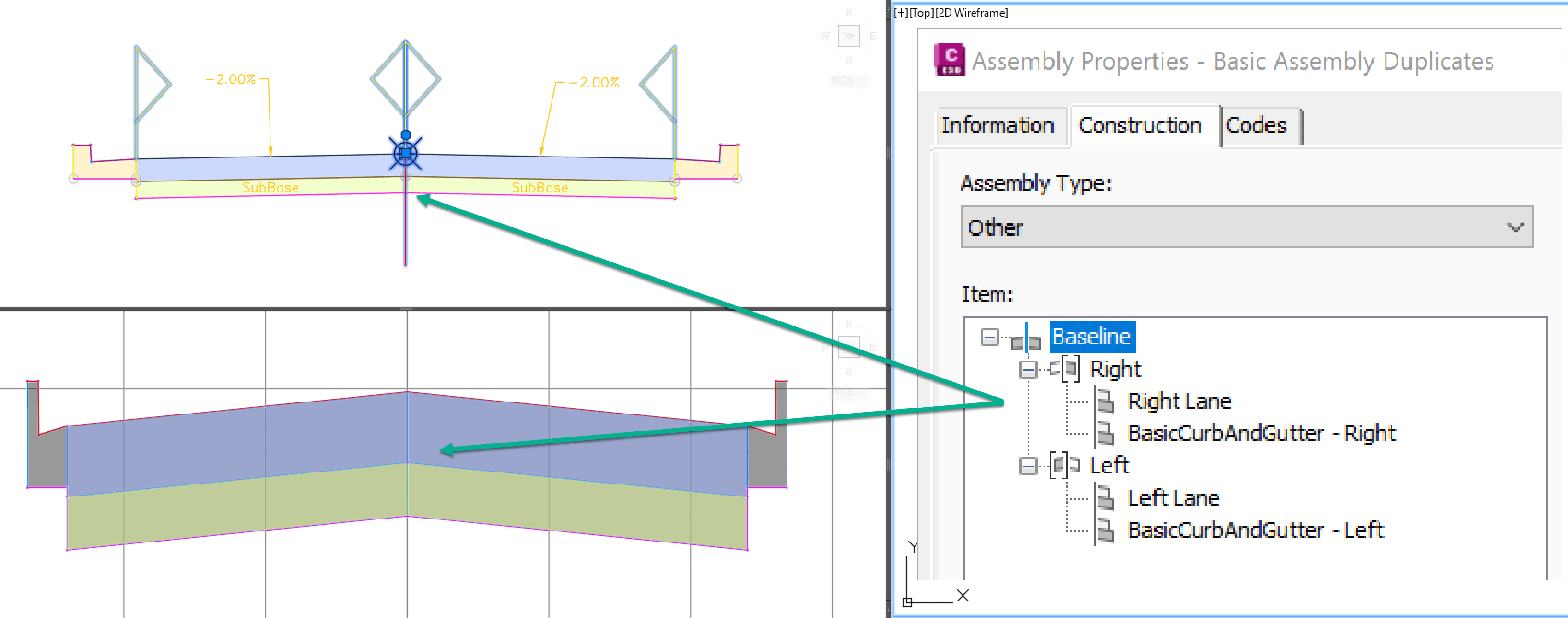
When subassemblies are duplicated there are 3 Lanes. When corrected only 2 are shown. The values are reduced by a third (33.33%) as shown in the tables below.
Reviewing the volume tables, the Lane subassembly shows the top pavement section Pave (shown in blue below) material on the LEFT shows corrected values and the RIGHT shows exaggerated values. 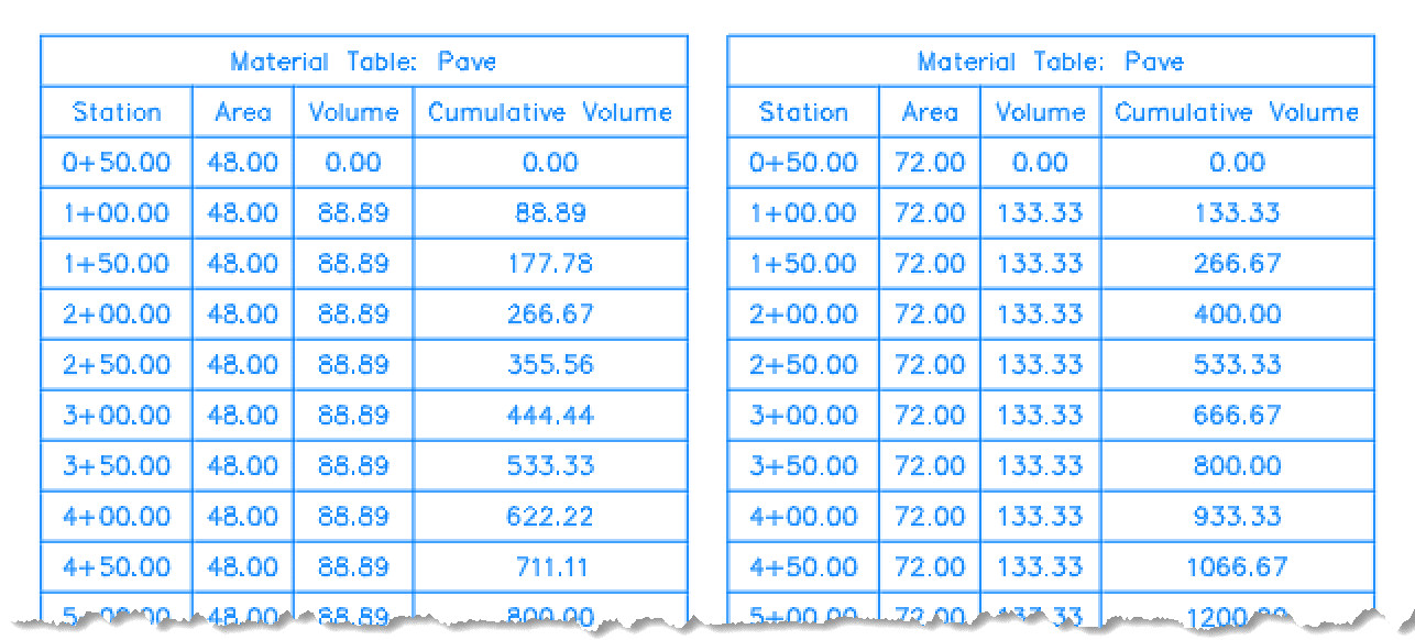
Similarly, the Lane subassembly shows the bottom pavement section SubBase (shown as tan) material on the LEFT shows corrected values and the RIGHT shows exaggerated values. 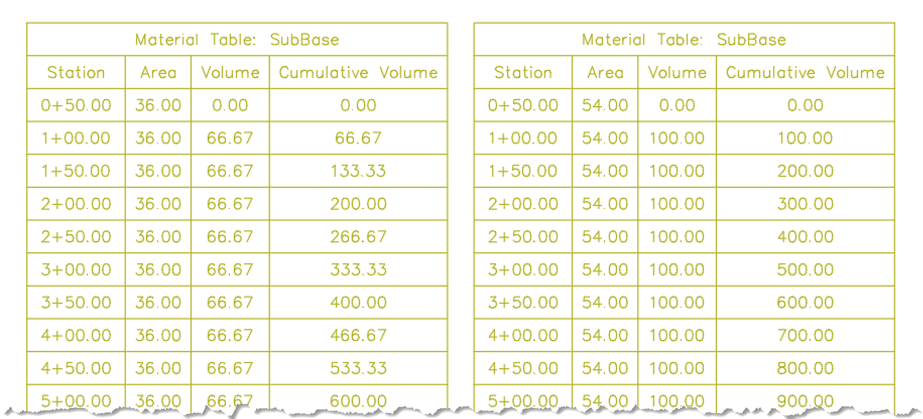
This is a simple example on how subassemblies can be duplicated and corrected in layout. Keep track of the details of how Assemblies are constructed as these will play a role in design, delivery and calculations.
About the Author
More Content by Leo Lavayen


