
There are many posts showing the use of refence text, here users will learn how to show Horizontal and Vertical values in a single annotation. Below are two examples using “Reference” text components in Civil 3D labels.
Example 1: Surface Spot Elevations and Alignment Station Values
Here a Surface Spot Elevation has a Reference text component added for an Alignment object. 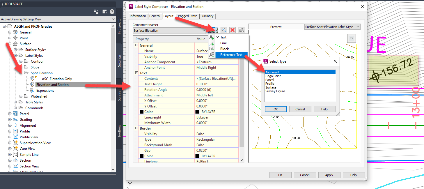
When the Reference Text is created, edit the Contents and add a “Station Value” component. 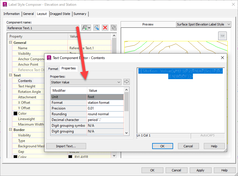
Note, when the labels will by default show “???”. The reference Alignment element still needs to be set from the AutoCAD palette. Select the label(s) and see how it shows <none> 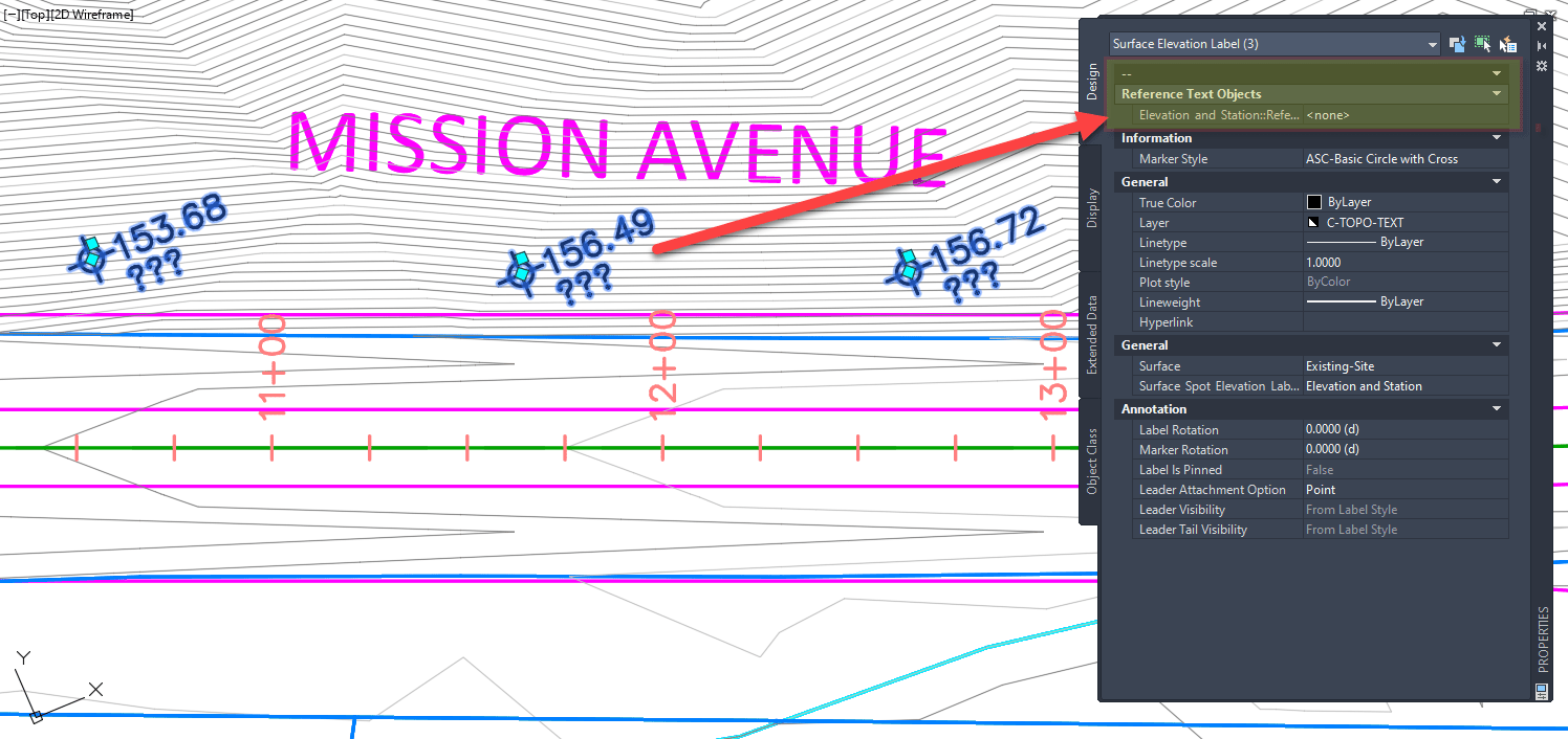
Once Alignment is set, station values will be shown as expected. 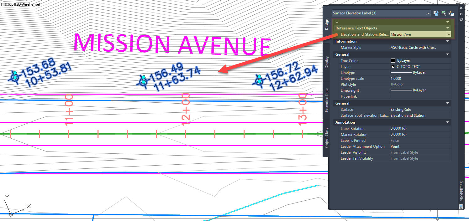
Example 2: Alignment Station Labels and Profile Elevation Values
Similar here a Major Stations will have a Reference text component added for a Profile object. 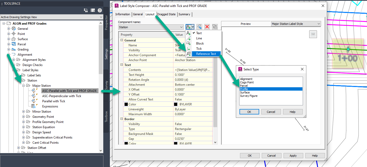
Once the Reference Text is created, edit Contents to add the “Profile Elevation” component. 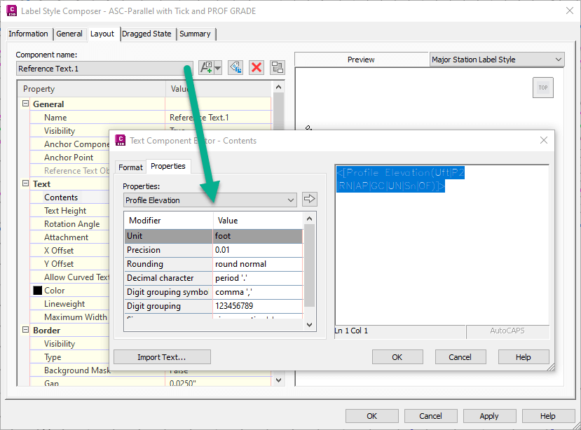
Again, when the labels are used by “???” are shown. The reference Profile element still needs to be set. Select the Label, then from the AutoCAD Properties palette see how it is set to <none> 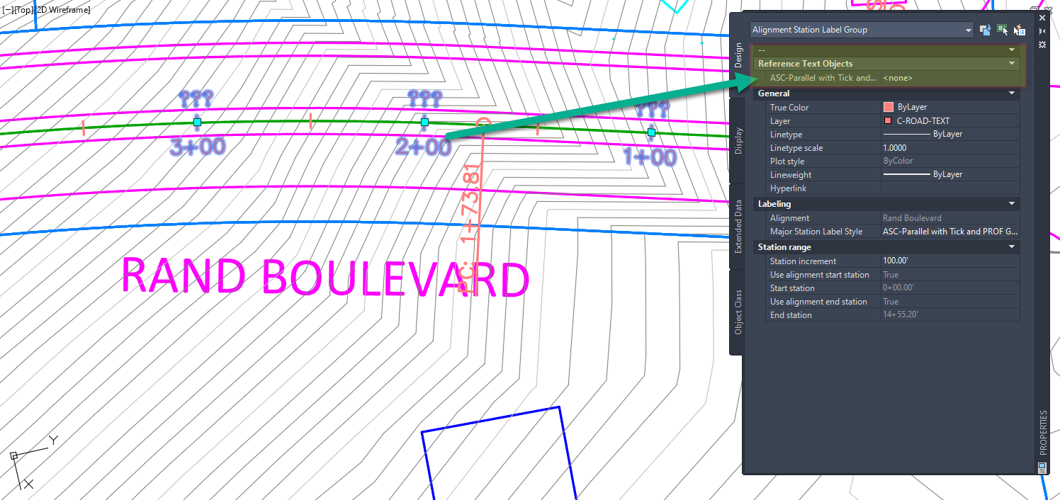
Once Profile is set, and based upon configuration, elevation values will be shown as expected. 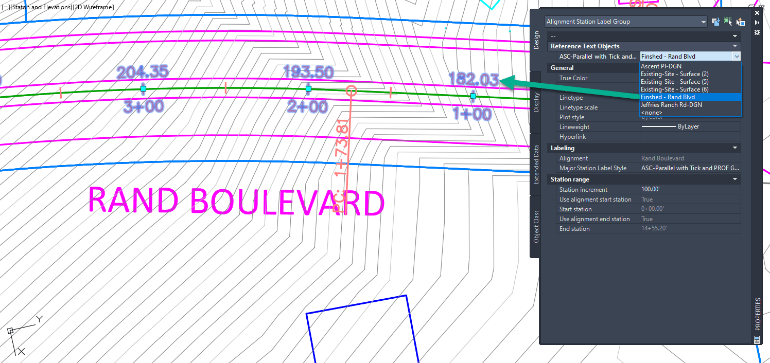
Simple configuration that allows users to reference data from one civil object to another civil object type. If configuration is something you are struggling with the IMAGINiT team can help.
About the Author
More Content by Leo Lavayen


