
Welcome to the last of four blog posts focusing on common Survey issues and how they are addressed in Civil 3D. In today’s blog we are learning how to move drawing content to a different coordinate system.
But first let’s explore the Universal Transverse Mercator (UTM) coordinate system.
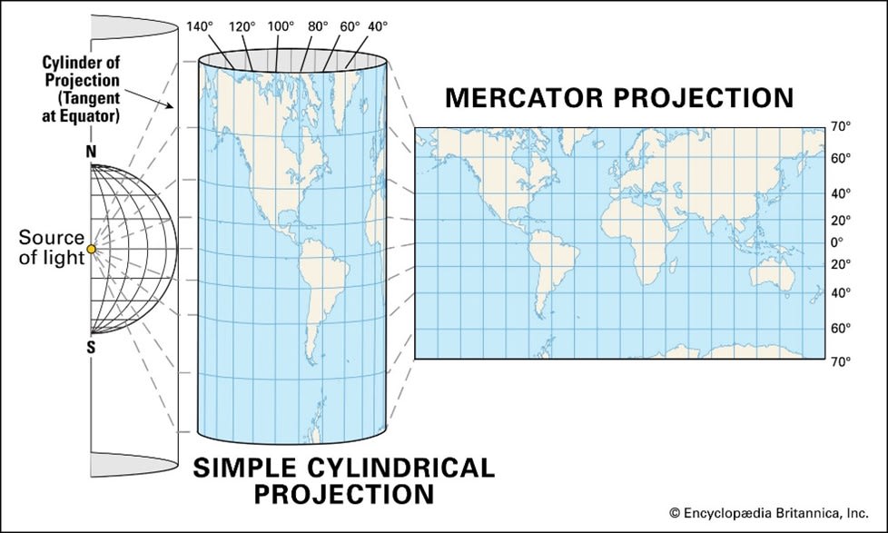
The UTM grid system is based on the Transverse Mercator projection. The Earth’s surface is projected onto a cylinder that is tangent to the equator. The cylinder is then unrolled to form a flat map.
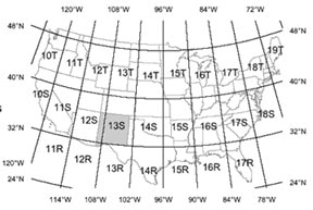
The UTM system divides the Earth into 60 zones. These zones are 6° of longitude, or 668 km, in width. The easting and northing coordinates of a position within a UTM grid zone are measured in meters, with the origin (0,0) located at the southwest corner of the zone. The easting coordinate is measured from the west edge of the zone, and the northing coordinate is measured from the south edge of the zone.
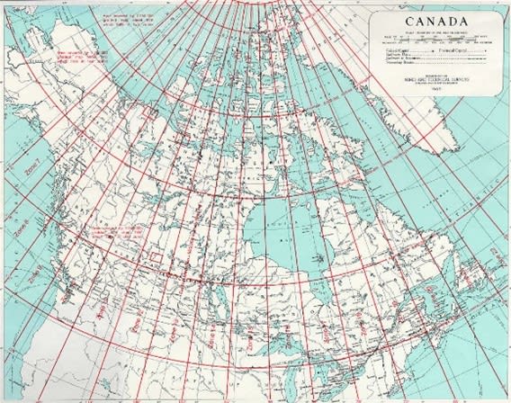
The UTM system minimizes distortion in each zone.
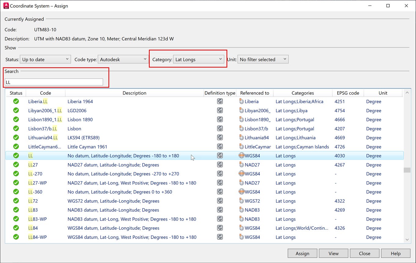
1. Type MAPCASSIGN in the command line. Search for the coordinate system you want to assign to your drawing file.
2. Switch to the Planning and Analysis workspace. This opens up the Map 3D commands and workflows within Civil 3D. The next four commands are found on the Map Explorer tab of the Task Pane.
3. Right-click on Drawings and select Attach. This is a Map 3D command that references files drawn in different coordinate systems.
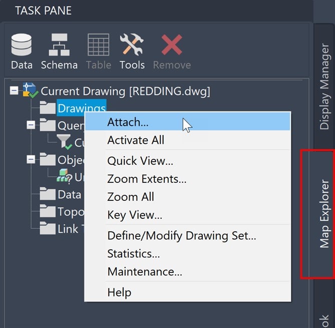
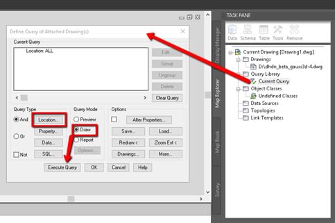
4. Create a Query with Location set to All and Query mode set to Draw.
5. Execute Query to insert the queried objects in the new drawing and transform to the current drawing coordinate system.
6. Right-click and Detach the source drawing from Task Pane on Map Explorer. The planimetric objects of the attached drawings remain in your current drawing.
Cogo Point Coordinate Transformations
Point Files can be transformed into a different coordinate system by creating a new Point File Format. This new Point File Format will be used to import into a drawing set up in the target coordinate system.
In the example I will use, my point file will be a PNEZD comma delimited txt file exported out of a drawing with the VA83-SF state plane coordinate system assigned. I will import this txt file into a drawing with UTM83-18IF coordinate system assigned.
- Open the drawing with UTM83-18IF assigned.
- In TOOLSPACE, click the Settings tab.
- Expand Point > Point File Formats.
- Select the PNEZD comma delimited Point File Format. Right-click and select copy.
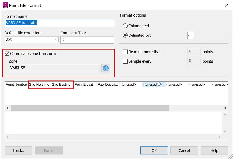
- Enter a new Format name. I will use the name: VA83-SF translate
- Select the Northing column and change the value to Grid Northing.
- Select the Easting column and change the value to Grid Easting.
- Select the Coordinate Zone Transform checkbox and then click the Globe button to choose the VA83-SF coordinate system.
- Click OK.
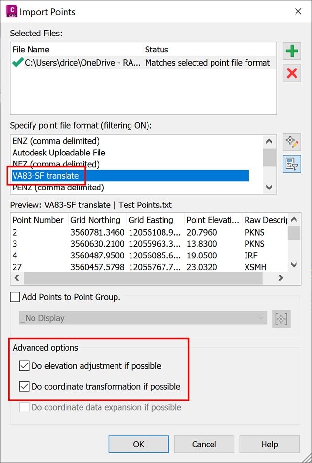
Now that you have the Point File Format created in the target drawing, you need to import the points. Once you’ve selected your point file, specify the VA83-SF translate Point File Format.
A very important step is to check both boxes under the Advanced Options.
That concludes our September Surveying Series. I hope this series was informative and helpful.
About the Author
Follow on Linkedin More Content by Dana Rice


