
In Autodesk Civil 3D, Design Speeds are managed from the Design Criteria tab within the Alignment Properties dialog box.
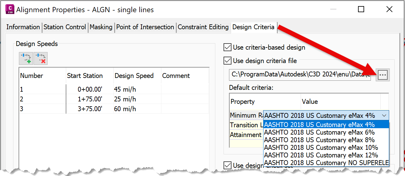
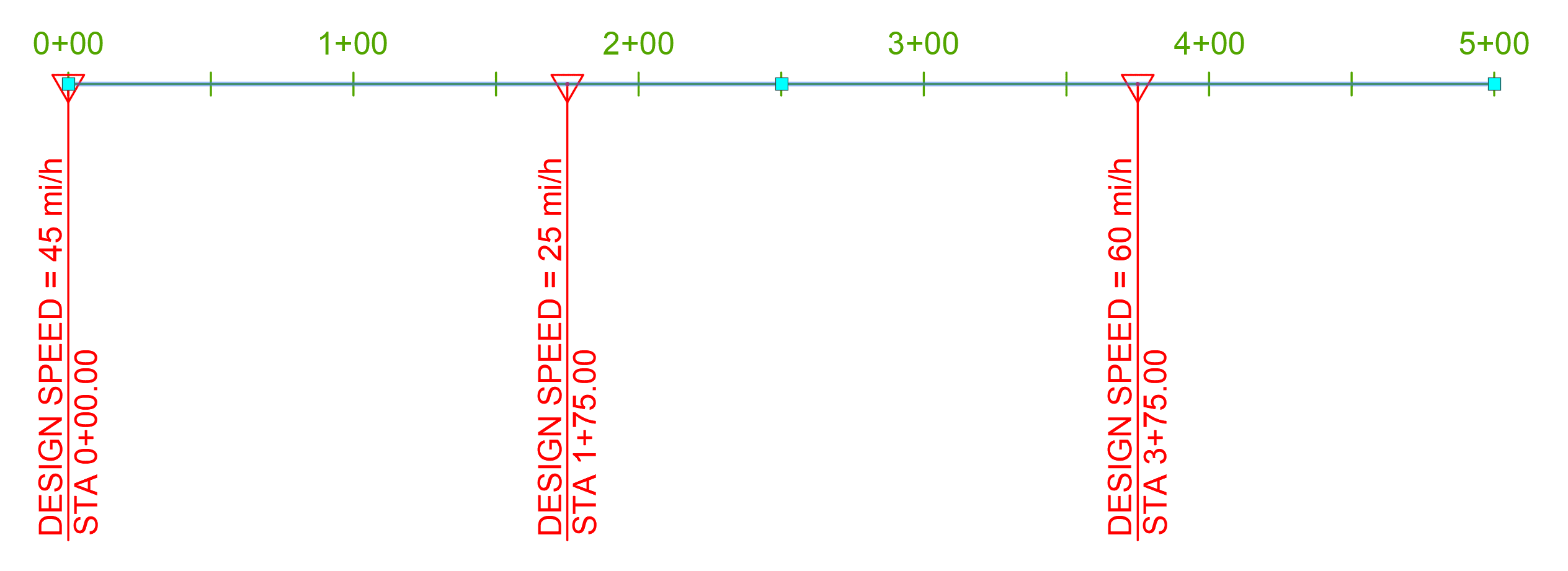
Once Design Criteria are assigned, Alignment Labels will display the corresponding station ranges and speed values along the alignment.
What Happens in Alignment Curves?
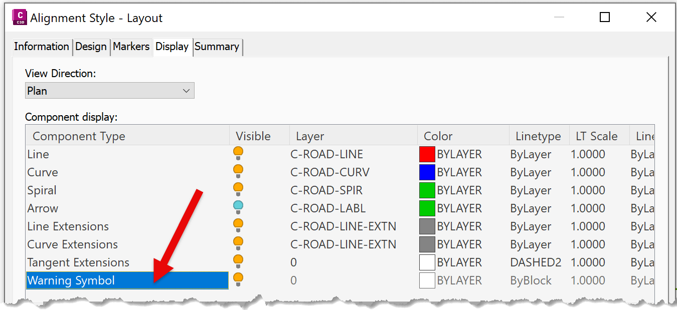
A key behavior to understand is what occurs when an alignment includes a curve and a Design Criteria file is applied. If the design falls outside of the defined parameters, Civil 3D will issue a ⚠️ warning, which appears on-screen (provided warnings are enabled in the style settings).
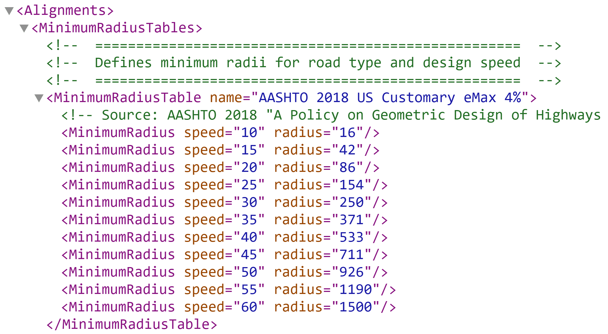
Below is an example showing the XML data from the ASHTO 2018 eMax 4% Design Criteria file. This table outlines the acceptable combinations of speed and radius values.
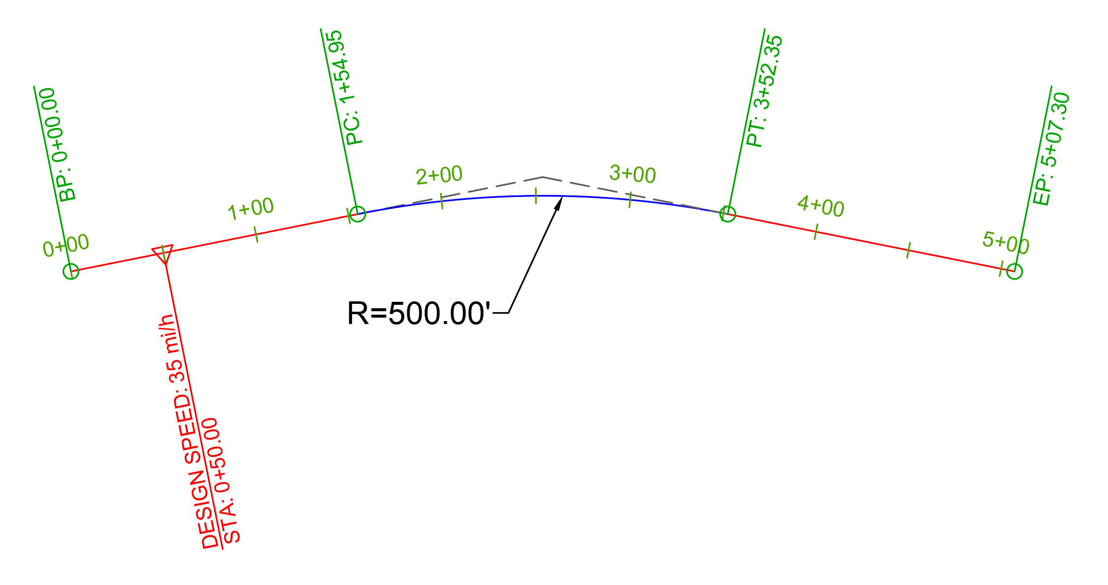
Example: Design Within Parameters
If a singular design speed is applied (e.g., set to 35 mph), it is applied from the alignment’s starting point onward. Using the ASHTO table, a 500’ radius at 35 mph meets ✅ design standards—no warnings are shown.
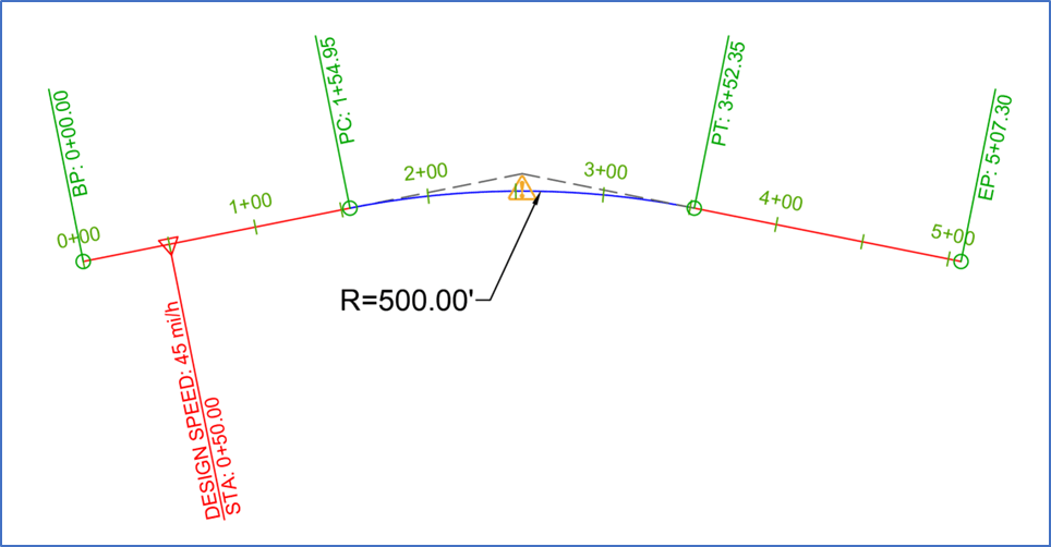
Example: Design Out of Compliance
However, if you change the speed to 45 mph while keeping the same 500’ radius, it falls outside the design criteria. As a result, Civil 3D flags the location with a ⚠️ warning.
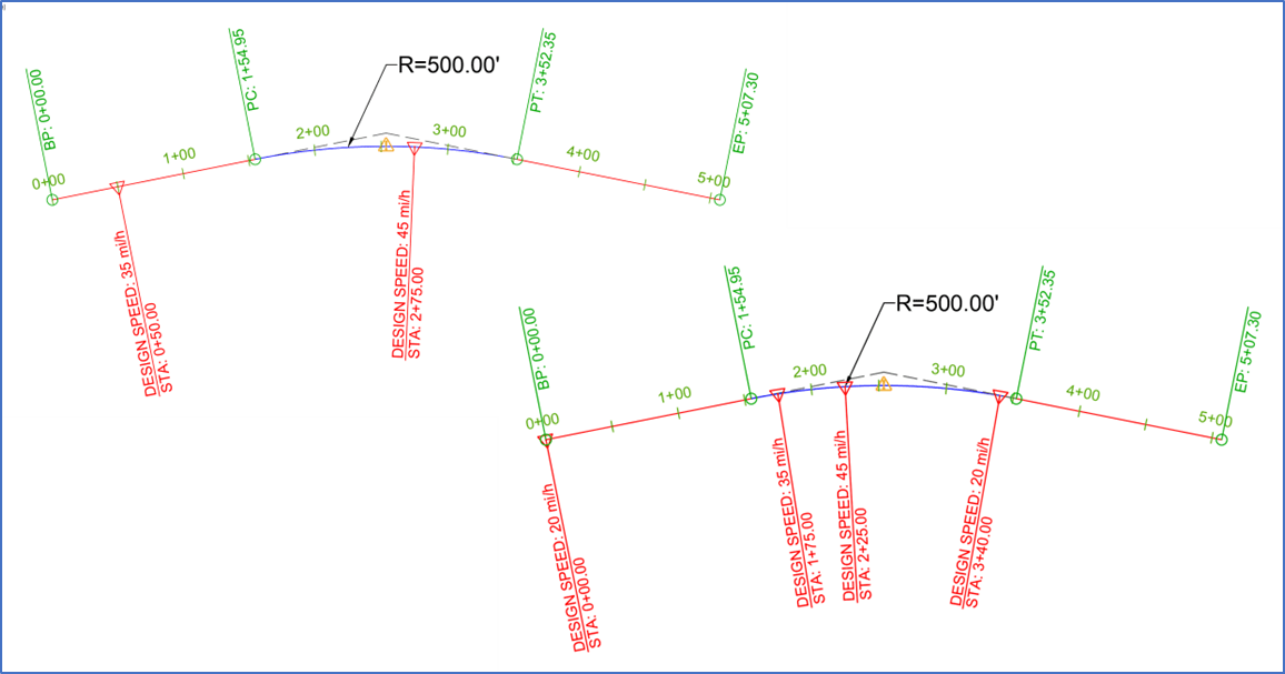
Similarly, if the design speed changes mid-curve and violates the criteria, Civil 3D will also display a ⚠️warning on that curve.
Final Thoughts
Understanding how Civil 3D applies and evaluates Design Speeds—especially in curved sections of an alignment—is essential for avoiding unexpected behavior or errors.
I hope this post helps clarify how design criteria and speed values interact in alignment curves.
About the Author
More Content by Leo Lavayen


