CAM (computer aided manufacturing), by definition, is the use of computer software to create the code and commands to drive CNC mills and lathes. It provides manufacturers the ability to automate machining operations that used to require tedious, manual inputs. This digital method has revolutionized the industry and changed how quickly, accurately, and safely parts can be made.
Similar to CAD, CAM allows the operator to visualize the way a part will look in a 3-dimensional workspace. The motion of tools and the material being removed can be simulated and perfected before setting foot on the shop floor. Adjusting the feeds, speeds, and other parameters in CAM reduces the inputs required on the machine controller. This all leads to a more efficient and more repeatable workflow.
Traditional CAM Workflow
In a traditional CAM workflow, there are several stages that require manual inputs and decisions. For each feature in a model (e.g. pocket, slot, hole) the operator must choose what strategy, boundary, tool, feed, and speed to use. Many decisions are made along the way as 3D geometry is dissected and converted into CNC toolpaths. More steps creates more opportunities to make mistakes. This process is also then repeated for every feature in the model. For large, complex parts this can be very time consuming.

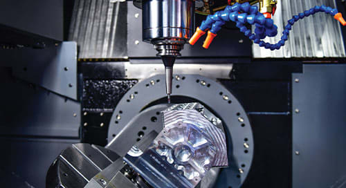
Naturally, the traditional CAM process leads to large amounts of tribal knowledge. There are so many decisions in the process that each operator will begin to form their own methodologies. Depending on how they were schooled, or what their background is, the resulting toolpaths and programs can become vastly different. There's no system in place for sharing knowledge to create consistent repeatable programs. For example, take the pocket feature on the part shown below:

Machinist "A" might choose to use a high-speed machining strategy to remove material in the pocket. They select a 1/4" flat end mill and use large step downs (depth of cut) and small step overs (width of cut). A pocket strategy is selected to finish the bottom and sides of the region. Because of the minimal tool load - the feed rate can be much faster. The total time to run the program is only 4 minutes and 30 seconds.
Machinist "B" programs it a different way. They decide to machine the pocket with a larger end mill (3/8") using small step downs. However, this strategy uses large step overs (width of cut) that will require a slower feed rate to avoid damaging the tool. They also choose a different ramp strategy (helix) that will likely be more optimal for this feature. The total time to run the program is around 12 minutes and 15 seconds.

At the end of the day, both programs will machine the pocket successfully. However, the second program takes 8 minutes longer. Once the remaining features are added, the time difference could be dramatic. There may also be some differences in the surface finish on the part that can lead to issues with quality control. Machinist "A" might discovered a better way to machine this feature, but traditional CAM software doesn't have the ability to standardize their approach. Autodesk FeatureCAM provides the automation and standardization required to solve these problems.
FeatureCAM Workflow
The biggest difference between Traditional CAM and FeatureCAM is automation. Instead of programming parts one operation at a time, FeatureCAM defines parts with features. A feature is a type of 3D CAD geometry like a pocket, boss, or slot. Once a feature is recognized by the software it will be broken up into the operations required to remove the material. The parameters, tools, feeds, and speeds are automatically determined from user preferences and material hardness tables.

FeatureCAM drastically reduces the number of steps and decisions in the CAM programming process. For example, when a threaded hole is recognized it will automatically be split up into a spot drill, rapid drill, and tap operation. The corresponding tools are selected based on hole diameter and stock material. That would required 3 complicated and independent strategies in the traditional workflow. After a feature is generated, the operator can still review and tweak parameters. Usually the updates are minor. Additionally, all the features in the model can be recognized simultaneously. The entire part can be programmed in a matter of 4 or 5 mouse clicks. The NC Code is automatically generated while the 3D stock removal simulation is running. Once the program is determined sufficient and safe - it can be sent to the machine for production.

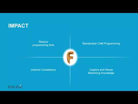
CAM Standardization and Automation with FeatureCAM
CAM programming without standardization is inconsistent and prone to errors, as demonstrated in the Machinist A / Machinist B example above. While automation is nice, it doesn't completely solve this problem. Fortunately, FeatureCAM can do much more than just automated feature recognition. Nearly every single parameter and machining attribute can be customized. User preferences can be set up in the Machining Configurations dialogue. This menu allows the operator to set the default, or preferred, value for every operation in the software. For example, the user can decide how holes should be drilled, what lead-in to use for pockets, what percentage of the tool diameter to cut with, etc.

The default settings for mill, turn, and wire strategies can be customized and applied globally. A new, independent machining configuration can even be created for each machine type, user, or scenario. CAM standardization can be achieved by creating a custom machining configuration and applying it company-wide. All the knowledge from the machinists, operators, and supervisors can be combined into an automated set of rules. When the software recognizes a feature, it will intelligently apply the rules to create a toolpath that is accurate, efficient, and repeatable. The programs built by Machinist A and Machinist B will be identical. The NC code will be identical. The run time will be identical. The finished parts will be identical.
To view the webcast related to this blog post - click here.
To learn more about purchasing Autodesk FeatureCAM - click here.
About the Author
Follow on Linkedin More Content by Ed Gillman