
The goal of this post is a walk through on how to create a AutoCAD dimension like label (shown as red below), instead of the default singular label for a for a corridor link (shown as green below). 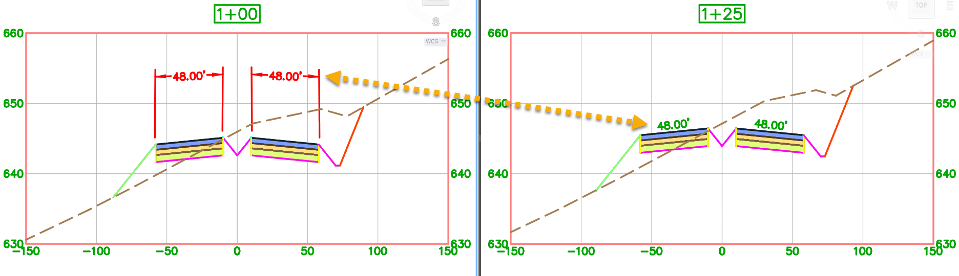
In this example label componentsare set to a color (red, green, blue, orange) for the configuration to stand out, it is not needed to work.
THE ISSUE
When building a dimension from a corridor link (pavement top in this case), it might create a skewed dimension. The dimension extension lines will be aligned to the base object. 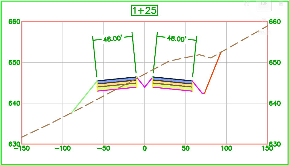
This post will show how to construct a label that looks more like a “linear” AutoCAD dimension label. The annotation will consist of 4 main components:
1. Left Dimension Line (start)
2. Right Dimension Line (end)
3. Horizontal Dimension Line (top)
4. Dimension Text (length)
BUILDING THE LABEL
Instead of working form the corridor element, the dimension lines will be based on the Section View Grid. Link labels allow set Anchor Point to: Top, Middle or Bottom. Referencing the grid will allow a uniform length and remove the “skewed” extension lines.
First, the Line.Left.Dim (shown as red) component:
• Start point is the “Start” of the corridor link <Feature>
• End point is the “Section View Top – at Start”.
• Lenth is set to “Percent Length” and set to 65% (this is users choice).
NOTE: how lines are duplicated on the left and right inside pavement codes for the lanes. 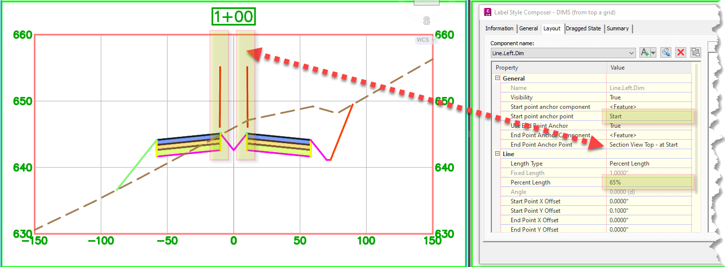
Next, the Line.Right.Dim (shown as green) component:
• Start point is the “End” of the corridor link <Feature>
• End point is the “Section View Top – at End”
• Lenth again is set to “Percent Length” and set to 65% (this is users choice)
NOTE: how lines are duplicated on the left and right outside pavement codes for the lanes. 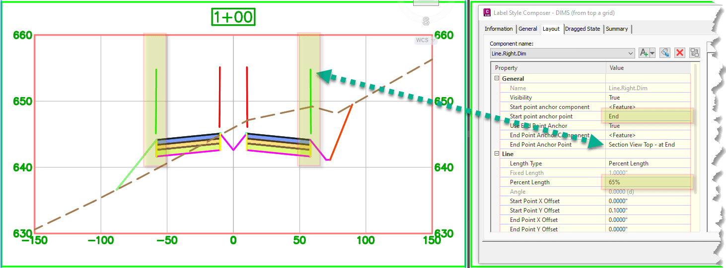 Then, the Line.Top.Dim (shown as blue) component.
• Start point is the “Line.Left.Dim” anchored to the “End”
• End point is the “Line.Right.Dim” anchored to the “End”
• Length remains at default 100% 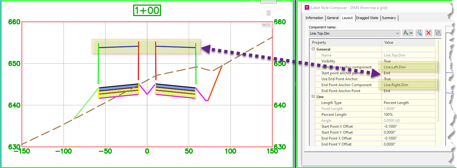
Last, the text Length component (shown in orange) component.
• Anchor Component is set to the previously created “Line.Top.Dim”
• Anchor Point is the “Middle”
• Length remains at default 100% 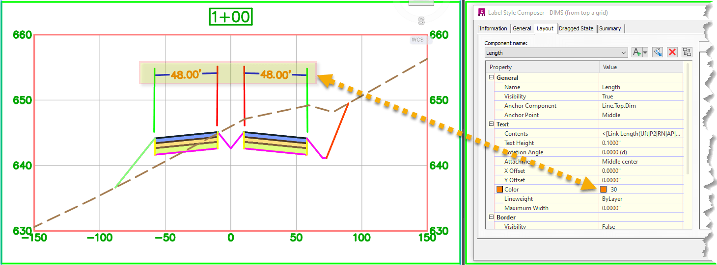
The label can then be put to use by assigning it to the corresponding link code in the Code Set Style. 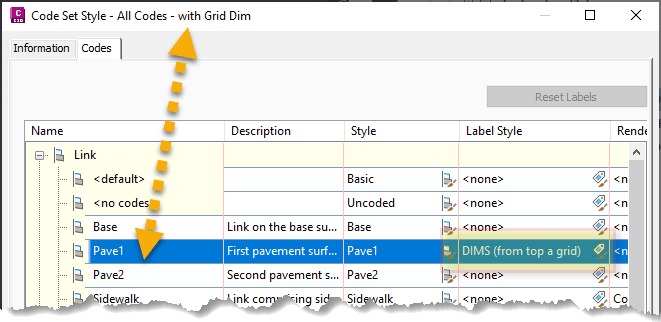
I hope this post helps you to create AutoCAD like dimension labels for corridor elements. If configuration is something you are strrguling with IMAGINiT can help. 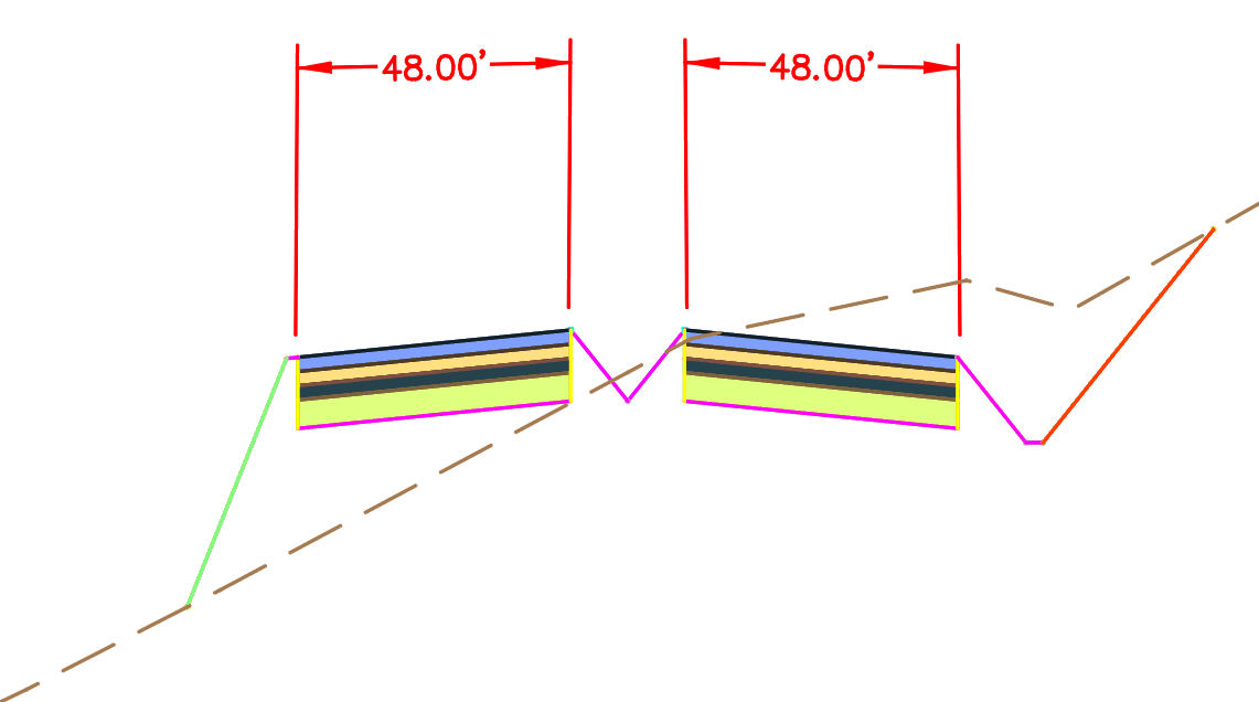
About the Author
More Content by Leo Lavayen


