Communication between a designer and other members of the project team is key to the successful implementation of a project. The Job/Work – Order tool in Substation Design Suite Protection and Control facilitates collaboration among team members and makes it easy for the designer to notify members of any changes or updates to an electrical drawing.
This tool is used to mark component symbols and wiring of an active project. You can assign a Job/Work Order number and a user status of “New”, “Remove”, “Revise”, or “Abandon” to the marked entities. They are assigned with their own layer and color. You can use this tool to set the status level on or off by manipulating the layer visibility.

Key Features:
- This tool will allow you to name the Job/Work-Order and mark Status of the group of components, devices, wires, text, and any symbols across all drawings in the AutoCAD Electrical “active” project.
- The project in AutoCAD Electrical can have one or many Job/Work-Orders running simultaneously. You can assign different statuses (such as Add, Remove, Revised, etc.) to different project components in the same drawing from a user-defined status name list (shown in the image below).
Note: You can mark components with only one Job/WO number and a status combination at a time.

3. All Job/Work-Order and status assignments are maintained in the native AutoCAD Electrical project drawing set. The status updates on the entities are called xdata. The status assignments are saved when you close an AutoCAD Electrical project and are accessible when you open the project again.
4. This tool maintains a running total of the marked entities in a project scratch database. You can click the Update Counts button and the tool will display the most up-to-date information in a table as shown below.
Note: The advanced features of the Job/WO tool are dependent upon the updated database table, so it is important to ensure that the data in the table is current while using these features.

5. Marking or unmarking a parent symbol gives you the option to automatically update some or all child and related symbols to match the parent's new Job/WO and status.
6. When you use this tool, impacted annotation attributes on wiring diagram symbols are automatically marked with the correct Job/WO and status.
For example, if schematic terminal symbol TB:1 is marked for "Remove" on a Job/WO, wherever terminal TB:1 appears in an annotation in the associated wiring diagram, that annotation attribute will be marked with the same color and layer information as the schematic terminal symbol TB:1 was marked.
7. Close out a Job/WO with the Rename, Reassign, Erase, and Normalize utilities.
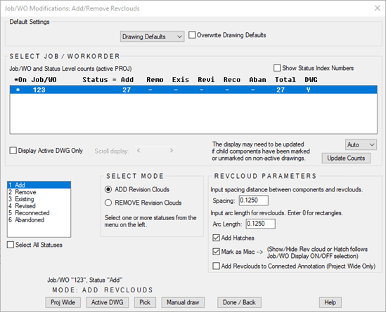
8. You can use this tool to add the Revision Clouds and Hatches feature to marked entities in Pick, Drawing Wide, and Project Wide modes. This feature automatically adds Revision Clouds and Hatches to impacted annotation attributes in the Project Wide mode.

Hope this blog helps you identify the main features of the Job/Work-Order tool. A more detailed study of this feature is available in the Substation Design Suite Protection and Control training course.


