
Welcome to the third of four blog posts focusing on common Survey issues and how they are addressed in Civil 3D. In today’s blog we will learn how to enter data into the Civil 3D Traverse Editor and convert that data by changing the units of measurement.
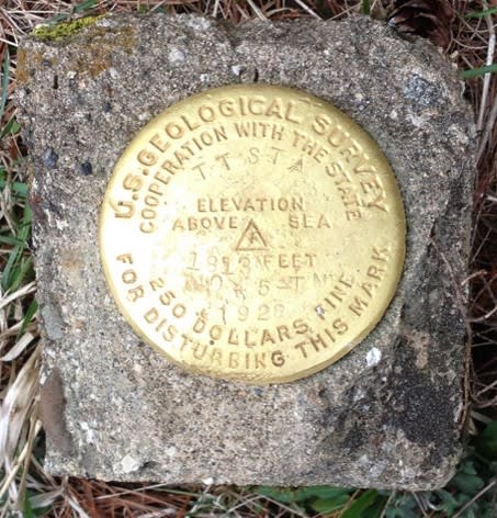
But first let us learn about survey benchmarks, which are reference points with precise vertical elevation and/or horizontal position. The elevation or position is usually established relative to sea level or a latitude/longitude baseline. Throughout the United States, permanent benchmarks are established by the U.S. Geological Survey, the U.S. Forest Service, the United States Army Corps of Engineers, and the National Geodetic Survey (formerly U.S. Coast & Geodetic Survey). Similarly, benchmarks have been established by various other federal, state, and municipal agencies, and by such private interests as railroads and water companies.
The NOAA maintains an interactive website of established benchmarks: NGS Map
Traverse Editor Data Entry and Conversion
The first data entry in the Traverse Editor must by a point. This will become the Point of Beginning (POB) of your traverse. Following that lines, points, and arcs can be entered into the Traverse Editor by selecting an existing polyline in the drawing or by manually entering known data.
Use the Tab, Enter, or arrow keys to navigate between cells.
Values entered in the Traverse Editor are not affected if the traverse is adjusted.
If an initial backsight is not specified, a default backsight of East (AutoCAD 0 degrees) will be used. Enter N or S in the Angle field of the first row if you want to start turning from an azimuth.
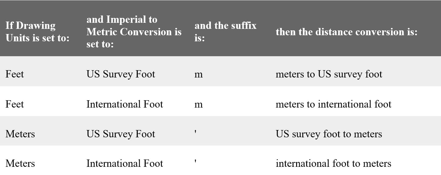
To use a unit of measure other than the current drawing unit, you can enter a suffix after the value. Enter the suffix directly after the value.
The following units are supported:
o Feet: '
o Meter: m
o Chain: c
o Rod: r
o Link: l
Converting between feet and meters depends on the parameters specified on the Units and Zone tab of the Drawing Settings dialog box:
Mathematical equations can be used to calculate traverse parameter values.
The following operators are valid; +, -, /, *
Next week we will learn how to convert drawings into a different coordinate system.
About the Author
Follow on Linkedin More Content by Dana Rice


